Plockmatic BM3050 system 27 August 2019 3. Repairs and adjustments (REP and ADJ)
3-60
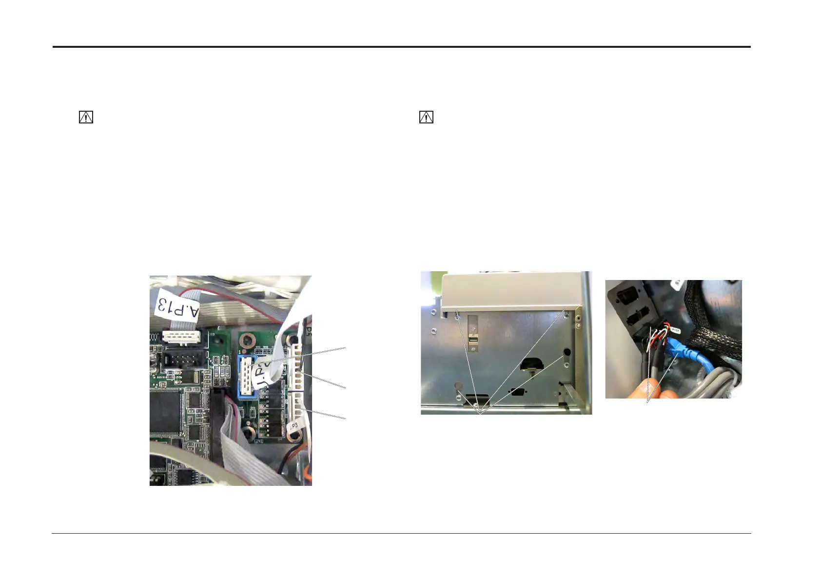
REP 7.6 User Interface assembly
Parts List on PL 2.0
Removal UI assembly
CAUTION:
ESD Hazard! ESD (Electrostatic Discharge) can cause hardware crashes, data and/or com-
munications problems. Failure to use proper ESD procedures will cause damage to electronic
components (example: PCBs). ESD problems can be minimized by maintaining all machine
ground connections, ensuring the proper handling of circuit boards/ sensors. Use ESD
protection when working near PCBs. Failure to use ESD protection is likely to result in a PCB
failure.
1. Turn off the main power and disconnect the power cord.
2. Remove the Front Cover (REP 1.1 Front and Rear Cover).
3. Remove screws (x4) [A].
4. Disconnect connectors P107 and ethernet [B].
5. Remove the UI assy.
Replacement
1. Reverse removal procedure.
NOTE:
If the User Interface assembly on the BM3050 is to be replaced,
the BM3050 upgrade kit should be transferred from the old User Interface assembly to the new one.
See installation instruction for how to install the upgrade kit.
[A]
[B]
REP 7.5 Expansion PCB ”J” 4 In 4 Out
Parts List on PL 3.1
Removal
CAUTION:
ESD Hazard! ESD (Electrostatic Discharge) can cause hardware crashes, data and/or com-
munications problems. Failure to use proper ESD procedures will cause damage to electronic
components (example: PCBs). ESD problems can be minimized by maintaining all machine
ground connections, ensuring the proper handling of circuit boards/ sensors. Use ESD
protection when working near PCBs. Failure to use ESD protection is likely to result in a PCB
failure.
1. Turn off the main power and disconnect the power cord.
2. Undock the Booklet Maker and Trimmer (REP 1.0 Undocking BM / TR / SQF).
3. Remove the Front Cover (REP 1.1 Front and Rear Cover).
4. Remove all connectors from the PCB (x3).
5. Pinch the barbs of the pins and remove PCB.
Replacement
1. Reverse removal procedure.
J.P3
J.P1
J.P2