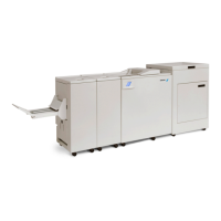
Plockmatic BM3050 system 27 August 2019 3. Repairs and adjustments (REP and ADJ)
3-108
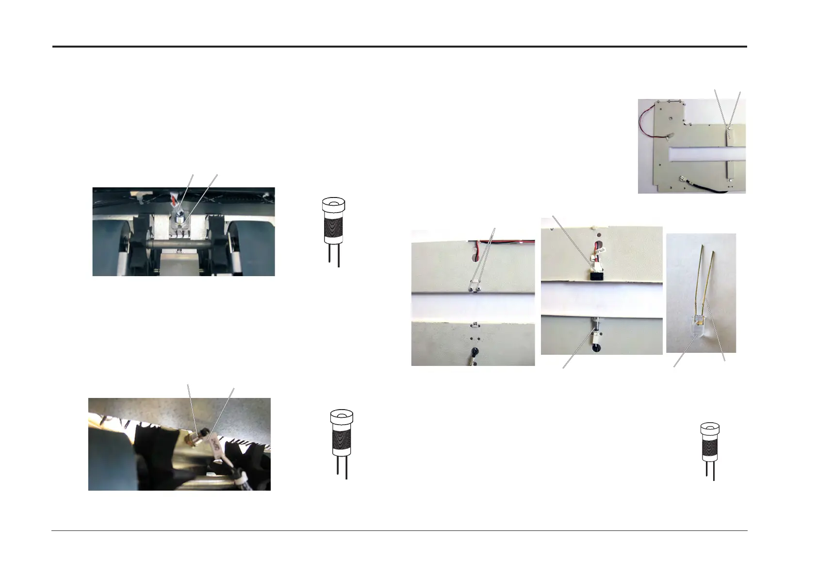
REP 11.13 SQF-Q5 Infeed Sensors
Replacement
1. Reverse removal procedure.
Parts List on PL 10.4
Removal SQF-Q5, LED
1. Turn off the main power and disconnect the power cord.
2. Disconnect connector [A].
3. Remove nut [B] (x1).
4. Remove LED.
Removal SQF-Q5, Phototransistor
1. Turn off the main power and disconnect the power cord.
2. Tilt the machine (REP 11.4 Tilt the Machine).
3. Disconnect connector [A].
4. Remove nut [B] (x1).
5. Remove Phototransistor.
Infeed Sensor
LED
Red
Black
Removal SQF-Q7, LED
1. Turn off the main power and disconnect the power cord.
2. Remove Lower Exit cover (REP 11.2 Exit Cover Assembly).
3. Remove screw and nut [A].
4. Remove cover [B]
5. Remove screws (x2) [C].
6. Remove bracket [D].
7. Remove LED [E].
Removal SQF-Q7, Phototransistor
1. Turn off the main power and disconnect the power cord.
2. Remove Lower Exit cover (REP 11.2 Exit Cover Assembly).
3. Remove cable ties [F].
4. Remove Phototransistor.
[A] [B]
[A]
[B]
Phototransistor
White Black
Infeed Sensor
REP 11.14 SQF-Q7 Exit Sensors
Parts List on PL 10.5
[B]
[A]
Replacement
1. Reverse removal procedure.
[D]
[F]
Phototransistor
White Black
Exit Sensor
[E]
BlackRed
LED
[C]


 To Next Page