Plockmatic BM3050 system 27 August 2019 4. Troubleshooting (RAP)
4-149
BM-152 30VDC High at Lower MD6DC PCB “C”
This RAP is for troubleshooting a high 30VDC at Lower MD6DC PCB “C”.
If this RAP frequently ends up with blown F1, go to F1 Blown Up RAP
Initial Actions
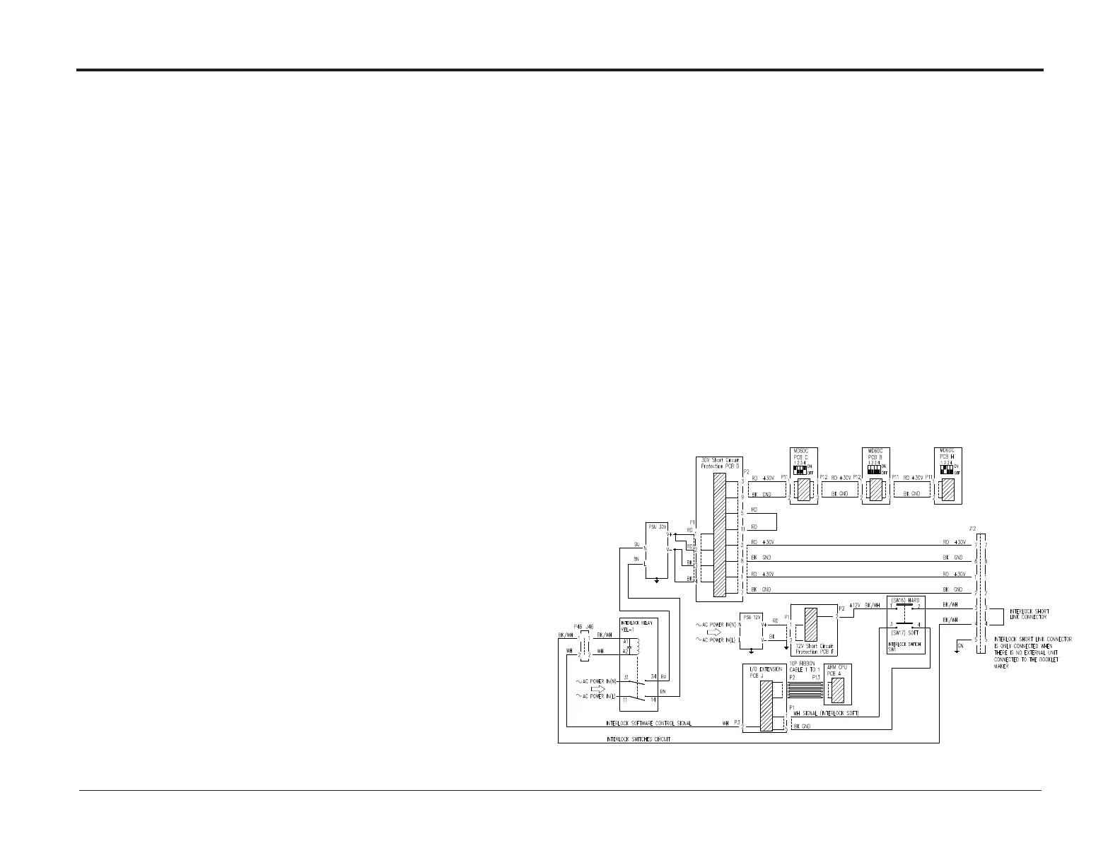
• Ensure that all connectors to SCP (Short Circuit Protection) PCB “D” (PL 3.0) are properly connected.
• Ensure that plugs/jacks related to 30VDC PSU (PL 3.1) are properly connected.
• Ensure that all connectors connecting to REL-1 are properly connected.
• Ensure that all connectors connecting to PCB “J” (PL 3.1) are properly connected.
• Ensure that connectors (Deburster K.P11) H.P11, B.P11, B.P12, C.P11, C.P12, A.P13, J/P12
and all connectors related to SW1 are properly connected.
• If a Square Folder/Trimmer is installed to the Booklet Maker,
ensure that A.P11, B.P2, D.P11, D.P12 and connectors related to SW1 in the Square Folder/Trimmer are properly connected.
• If a Square Folder/Trimmer is not installed, ensure that the short link connector is connected to Booklet maker J12.
Procedure
• Power on the machine and enter the service menu, close the top cover
• If there is a Square Folder/Trimmer connected close top covers.
• Measure between +V and –V at the 30VDC PSU,
adjust the trimmer potentiometer on the 30VDC PSU until you reached a value between 29.8-30.2VDC.
If you have no success adjusting the voltage, perform following in order:
• Load latest software version to ARM PCB “A” (PL 3.1).
• Replace ARM PCB “A”
• Replace 30VDC PSU (REP 7.8) (PL 3.0).