Plockmatic BM500 system 27 August 2019 6. Detailed Description
6-3
6.2.4 STAPLER AND STAPLE STOP GATE MODULES
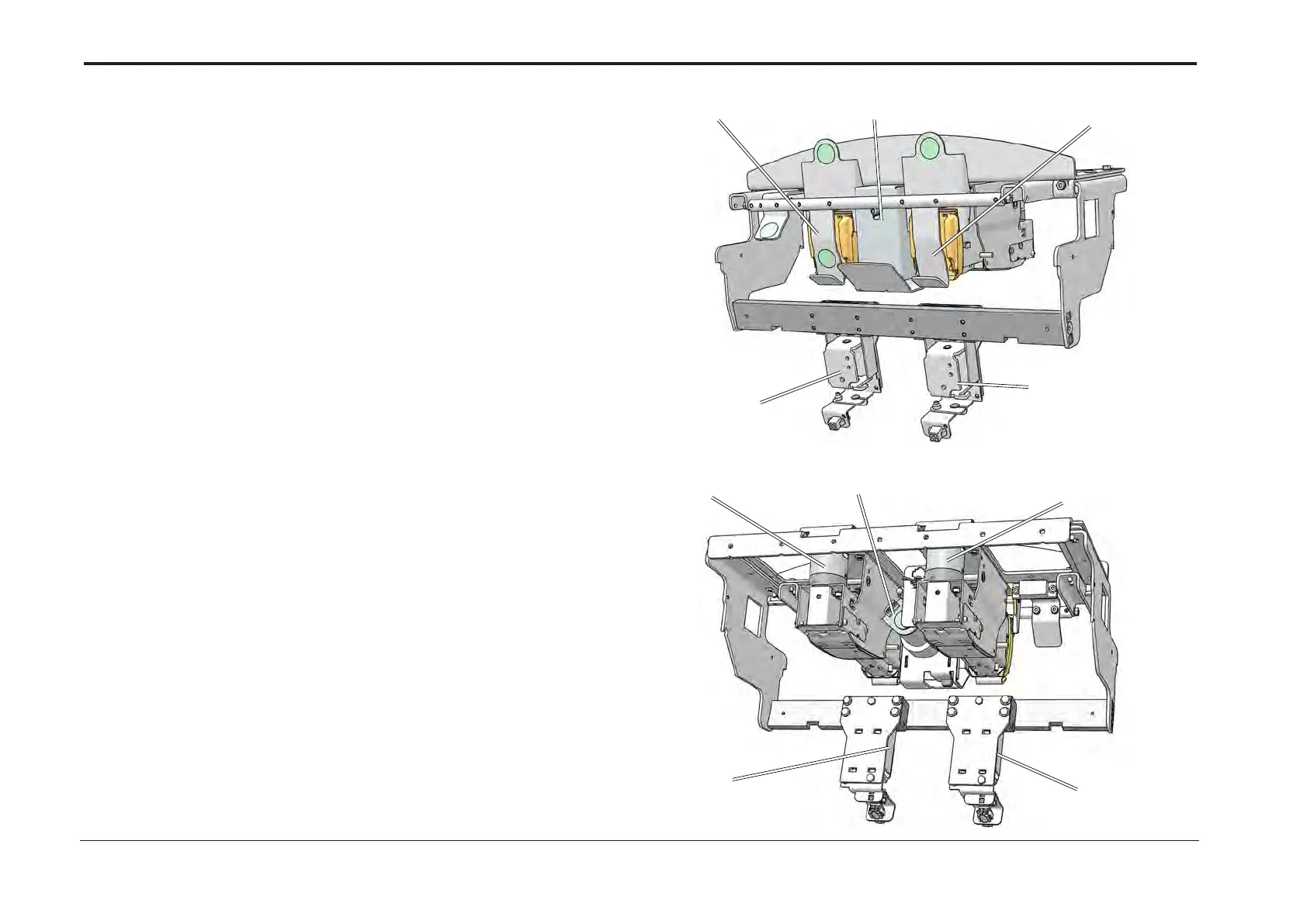
With the set jogged, The stapler motors M20 and M21 cycles,
putting staples through the set.
When the staples are driven through the set, a trig signal,
Sensor Q48 and Q51, from the stapler, starts the corresponding clincher solenoid,
which bends the staple legs to be at.
When the staples contact the clinchers,
a closed circuit is established through Q19 and Q20,
by current running from stapler head through staple contacting the clincher.
The closed circuit created, indicates that staples are present.
If no staple is present the paper will insulate the stapler head from the clincher,
which will result in an open circuit.
The open circuit at this time will indicate, staple miss.
The stapler motors M20 and M21 will complete its cycle and stop in upper
position as the stapler home position sensors Q47 and Q50 activates.
Each staple head also has a Low Staple Sensor, Q46 and Q49.
The BM is also equipped with Thick Set Sensing device located between the staplers
(motors M20 and M21).
Throughout the compiling sequence the Booklet Maker will
measure the set thickness to prevent too thick sets to pass through the system.
This is done by motor M23 and sensor Q36 that senses thickness of set.
This sensor also provides info to adjust staple-line,
trim length as well as square fold mode.
M23 and Sensor
Q36 (M23 home)
M20 (including
Q49, Q50 and
Q51)
M21 (including
Q46, Q47 and
Q48)
BK-clinch left
solenoid
(including Q19)
BK-clinch right
solenoid
(including Q20)
M23 and Sensor
Q36 (M23 home)
M20 (including
Q49, Q50 and
Q51)
M21 (including
Q46, Q47 and
Q48)
BK-clinch left
solenoid
(including Q19)
BK-clinch right
solenoid
(including Q20)


 To Next Page