Plockmatic BM3050 system 27 August 2019 4. Troubleshooting (RAP)
4-405
RAP 043 SP Sensor
This RAP is for troubleshooting a non functional SP Sensor.
The primary objective is to decide if the failure is related to PCBs, the sensor or harness.
Initial Actions
• Enter service mode according to GP 1
• Check sensor (GP 4)
• Ensure that the sensor is clean
• Ensure that all connectors at the SP Sensor are properly connected
• Ensure that all connectors at PCBs are properly connected
• Ensure that DSD sensor is calibrated (BM 3050 Operators Manual, VF602 Sensor Cali-
bration Section)
NOTE!
FormeasuringreferencesandconnectorsidenticationseeBSD
Procedure
WARNING!
Turn off the VF602 Main Power Switch and disconnect the Main Power Cord before
disconnecting, removing or replacing any electrical components or measuring
resistance inside the machine.
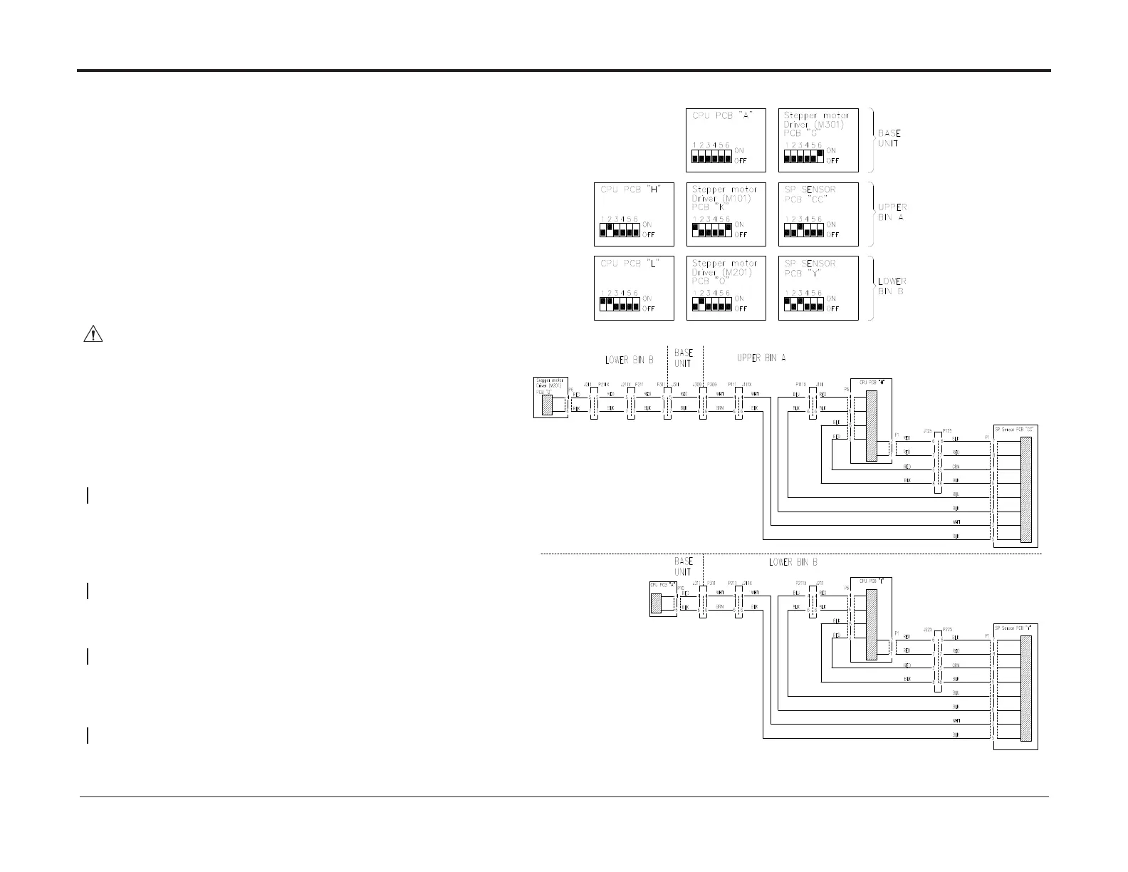
Power off the machine, disconnect connectors described in the BSD at both CPU PCBs
and at the SP Sensor. Measure continuity for wires between SP Sensor and both CPU
PCBs. Check for short circuits between all wires and between all wires to chassis described
in the BSD:
There is continuity and no short circuit
Y N
Repair/replace harness
Swap the faulty SP sensor with one in the other bin.
After swapping the sensor, set the address DIP switches to settings in the circuit diagram.
Check sensor functionality
Sensor works at new location
Y N
Replace sensor
Perform RAP 006 ICAN Circuit
Success
N Y
Exit
Perform RAPs for both related CPU PCBs (skip the part that guides you back to RAP SP
Sensor)
Success
Y N
Replace the SP Sensor (REP 15.35)
Exit