SV-EMS-220/221 Installation and Configuration
SkyView System Installation Guide - Revision AA 7-47
Tachometer
Tachometer pulses/revolution are set in the Engine Information Wizard – SETUP
MENU > HARDWARE CALIBRATION > EMS CALIBRATION > TACHOMETER
CALIBRATION.
Dynon Avionics does not sell a tachometer transducer.
Depending upon existing equipment and engine type, you have a few options for connecting
the tachometer inputs on the SV-EMS-220/221. Table 51 revisits the SV-EMS-220/221 pins that
are compatible with RPM sources.
Standard RPM Input Left (10+ volts)
Standard RPM Input Right (10+ volts)
Low Voltage RPM Input Left (< 12 volts)
Low Voltage RPM Input Right (< 12 volts)
Table 51 – SV-EMS-220/221 RPM Inputs
See the relevant subsections below for your particular method. You may connect different
types of signals to the two different RPM inputs (e.g., p-lead to Standard RPM Left and a 12 volt
transducer to Standard RPM Right).
SkyView will display RPM from either the RPM Input Left or the RPM Input Right, whichever is
noticed by the SV-EMS-220 first. If the first RPM signal is lost (such as when one ignition source
fails, or during a routine mag check), then SkyView will display RPM from the remaining RPM
signal. If your engine only provides one RPM signal, connect it to one of the two RPM Input Left
pins.
Pin 32 and Pin 34 are both LEFT RPM input. Use one, or the other, but not both.
Pin 33 and Pin 35 are both RIGHT RPM input. Use one, or the other, but not both.
Tachometer transducer
If you have a dedicated tachometer transducer (usually with a 12 volt output), you may simply
connect its output to the Standard RPM Left input on the SV-EMS-220/221. Ensure that you
follow all recommendations given in the manual for your individual tachometer transducer.
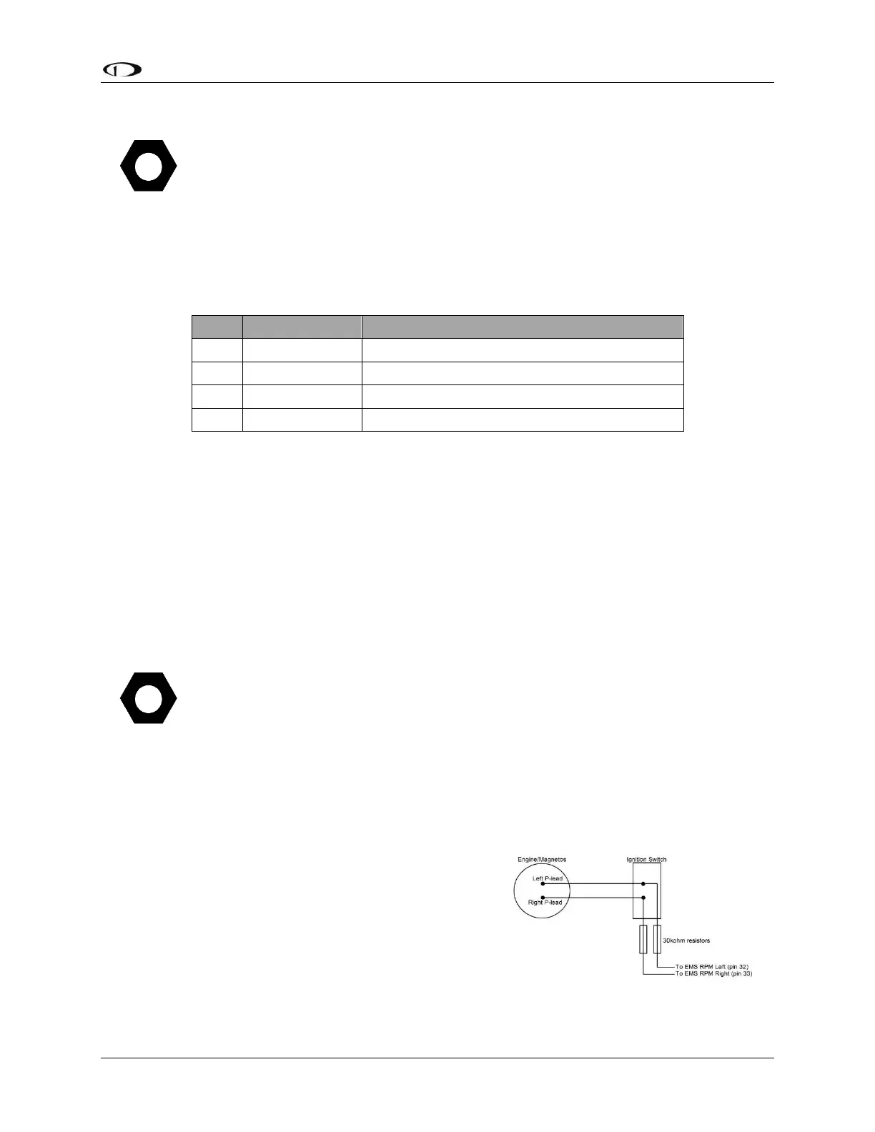
P-lead pickoff (Lycoming and Continental)
If you do not have a dedicated tachometer pickoff, you
must follow the instructions below.
Use the two included 30 kΩ resistors (color bands:
orange, black, brown, red, brown; connect in either
direction) to attach left and right P-leads to the standard
RPM Left and RPM Right inputs on the SV-EMS-220/221.
Figure 62 – Magneto Pick Off