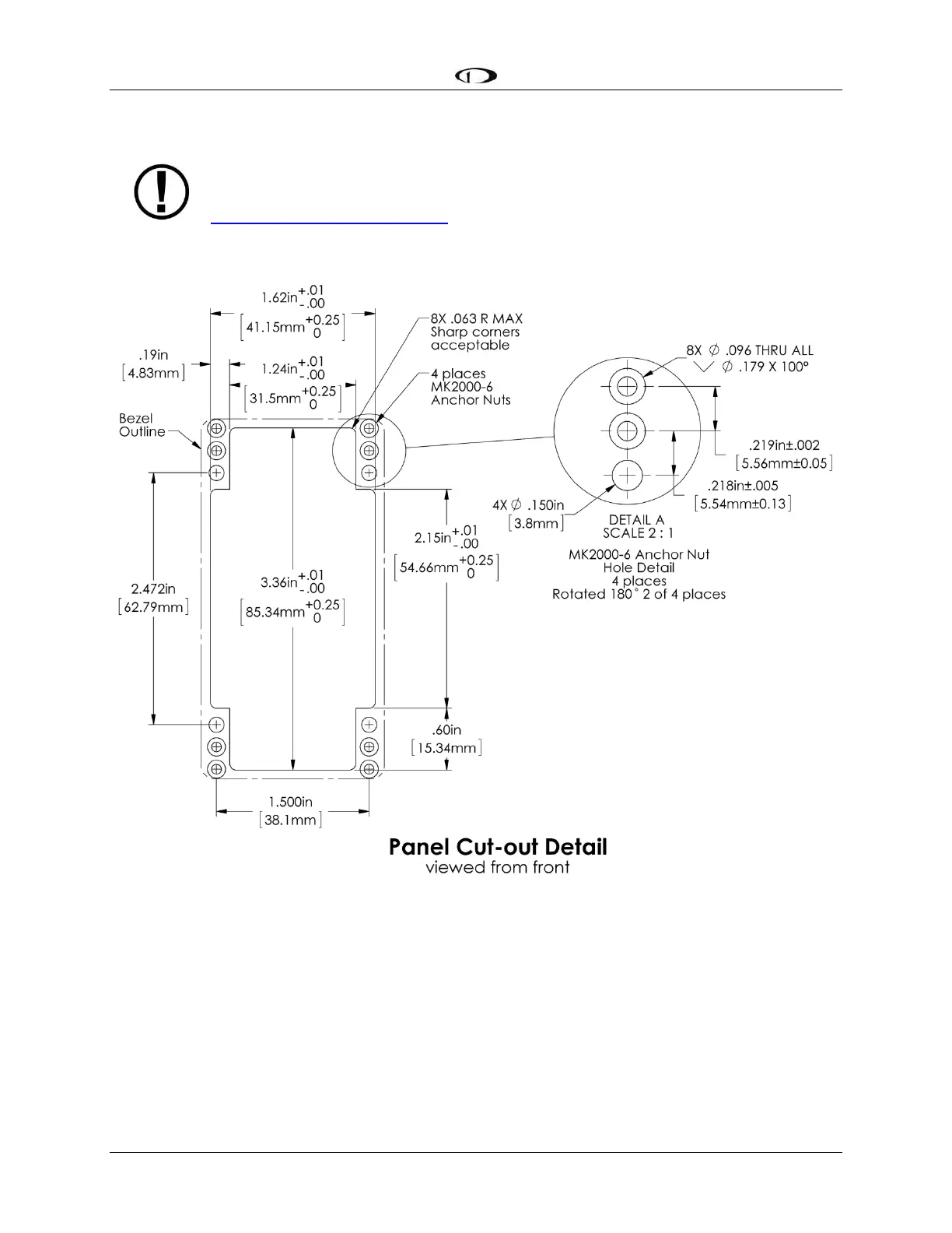
The following diagrams are NOT to scale. However, paper templates are included
with your SV-COM-C25 and may also be downloaded from
http://docs.dynonavionics.com.
Figure 186 – SV-COM-PANEL - VERTICAL Panel Cutout and Mounting Hole Dimensions - NOT ACTUAL SIZE
Physical Installation: SV-COM-T8
The figures on the following pages show mechanical dimensions for the SV-COM-T8.
The following installation procedure should be followed to install the SV-COM-T8 remote
transceiver module, remembering to allow adequate space for installation of cables and
connectors.