SV-COM-C25 Installation and Configuration
SkyView System Installation Guide - Revision AA 16-15
Optional Flip / Flop Button
Pin 7 of the SV-COM-PANEL can be connected to a Push Button Normally Open (PBNO) and
GROUND. Pushing this button “flip flops” the ACTIVE and STANDBY frequency selection - the
same function as pressing in the TUNE knob on the SV-COM-PANEL. Typically, this signal is used
with a button on the stick.
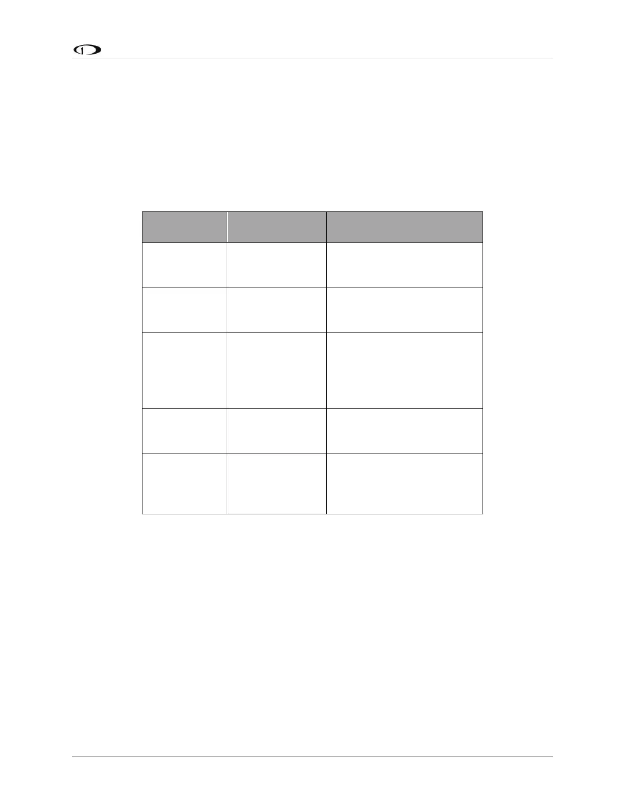
Phones / Headset Connections for SV-INTERCOM-2S
Table 93 – Phones / Headset Connections for SV-INTERCOM-2S
To avoid noise, hum, and other undesirable signals, always use shielded cable for any low-level
audio signals such as microphone inputs, and connect the shield of the cable as directed.
Antenna Installation
Dynon Avionics does not supply COM antennas, radio coaxial cable, or antenna BNC
connectors. The antenna (including coaxial cable and connector) should be installed according
to the manufacturer’s instructions.
The following considerations should be taken into account when siting the antenna:
The antenna should be well removed from any projections, the engine(s) and propeller(s). It
should also be well removed from landing gear doors, access doors or others openings
which will break the ground plane for the antenna.