Appendix C: Wiring and Electrical Connections
23-18 SkyView System Installation Guide - Revision AA
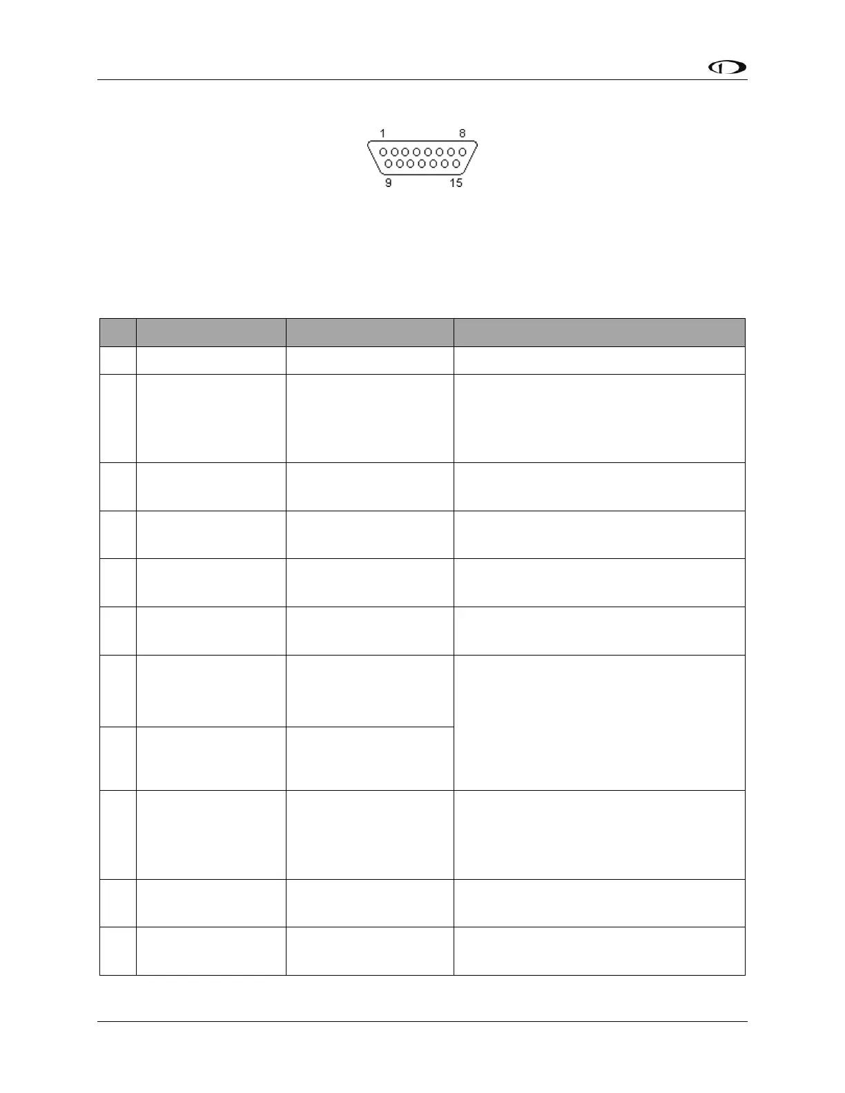
SV-AP-PANEL Pinout (D15M connector)
Figure 224 – SV-AP-PANEL D15F Connector Pin Numbering
The SV-AP-PANEL Trim Control Subsystem uses a D15M connector for connecting to trim
control buttons, the trim servo(s), and power for the trim servos(s). Figure 224 above shows the
pin numbering for the mating D15F connector, installed on the cable that plugs into this
connector, from the rear (pin insertion) view.
(determined by installer)
If trim motor(s) control is not used, do
not connect. Power and ground for the
SV-AP-PANEL front panel buttons is
provided by SkyView Network.
Motor 1: Pin 7 polarity is +
Pin 8 polarity is -
(determined by installer)
Motor 1: Pin 7 polarity is –
Pin 8 polarity is +
(determined by installer)
Motor 1: Pin 7 polarity is +
Pin 8 polarity is -
(determined by installer)
Motor 1: Pin 7 polarity is –
Pin 8 polarity is +
(determined by installer)
Pin 3 or Pin 5 grounded: Pin 7 polarity is
+, Pin 8 polarity is - (Motor rotates in
one direction)
Pin 4 or Pin 6 grounded: Pin 7 polarity is
-, Pin 8 polarity is + (Motor rotates in the
other direction)
(determined by installer)
If trim motor(s) control is not used, do
not connect. Power and ground for SV-
AP-PANEL front panel buttons is
provided by SkyView Network.
(determined by installer)
Motor 2: Pin 14 polarity is +
Pin 15 polarity is -
(determined by installer)
Motor 2: Pin 14 polarity is -
Pin 15 polarity is +