SV-COM-X83 Installation and Configuration
17-16 SkyView System Installation Guide - Revision AA
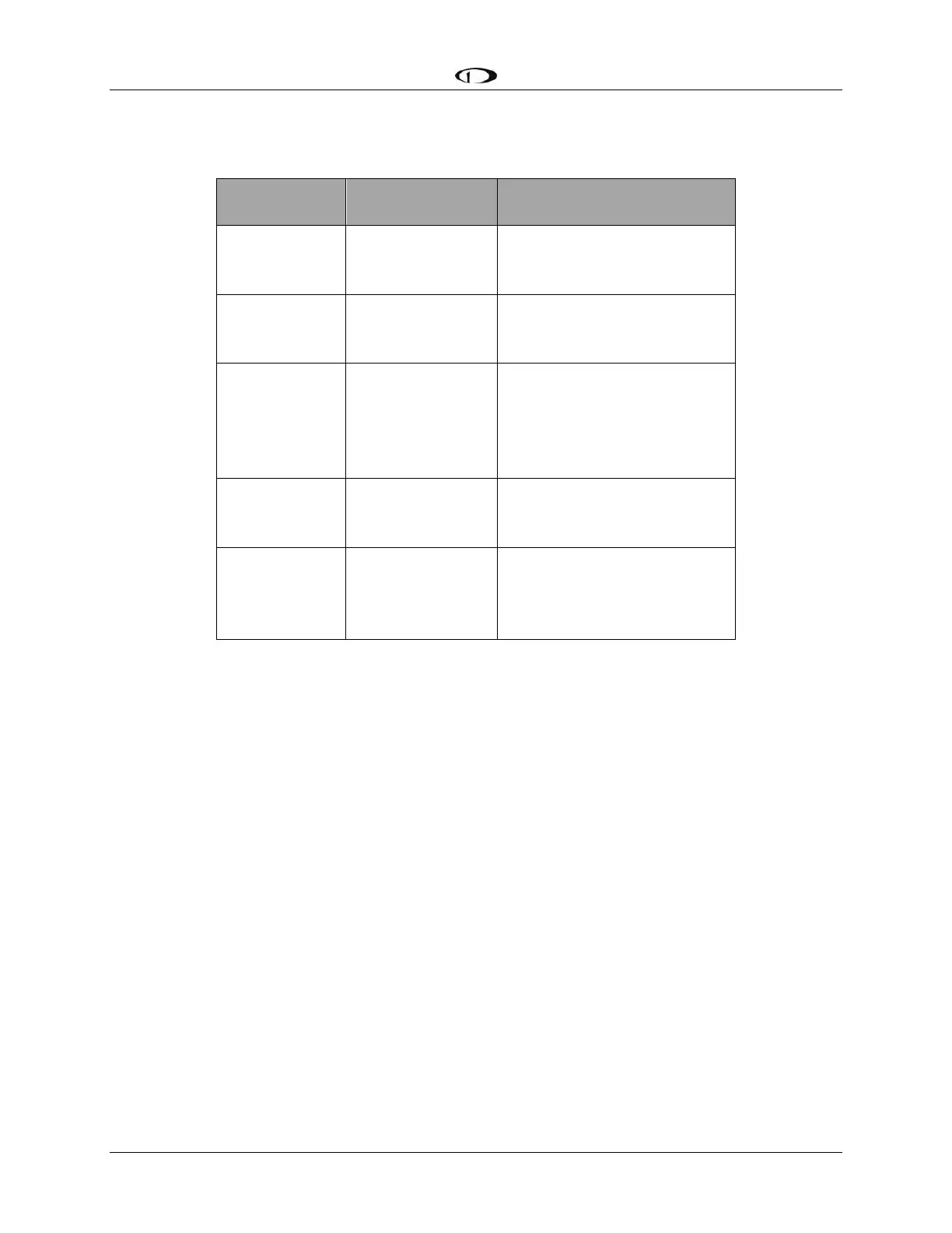
Phones / Headset Connections for SV-INTERCOM-2S
Table 97 – Phones / Headset Connections for SV-INTERCOM-2S
To avoid noise, hum, and other undesirable signals, always use shielded cable for any low-level
audio signals such as microphone inputs, and connect the shield of the cable as directed.
Antenna Installation
Dynon Avionics does not supply COM antennas, radio coaxial cable, or antenna TNC connectors.
The antenna (including coaxial cable and connector) should be installed according to the
manufacturer’s instructions.
The following considerations should be taken into account when siting the antenna:
If two COM radios (including SV-COM-C25 or SV-COM-X83) are installed, the two COM
antennas should be installed as far apart as practical, ideally installing one COM antenna on
the upper fuselage and the other COM antenna on the lower fuselage.
The antenna should be well removed from any projections, the engine(s) and propeller(s). It
should also be well removed from landing gear doors, access doors or others openings
which will break the ground plane for the antenna.
Separation of COM antenna(s) from transponder(s) and GPS receivers / antennas: 2 feet (24
inches).