System Planning
SkyView System Installation Guide - Revision AA 2-17
Note, that in Figure 9, each SV-GPS-250/2020’s power, ground, and output wires
are connected to both displays on different serial ports. The primary SV-GPS-
250/2020 should be connected to serial port 5 on each display. The secondary SV-
GPS-250/2020 should be connected on another serial port on each display.
Additionally, if there are both multiple displays and multiple SV-GPS-250/2020
units in the system, power for the secondary GPS should be sourced from the GPS
power wire on the second display – in other words, each SV-GPS-250/2020 should
receive power from a different display. Reference the SV-GPS-250/2020 GPS
Receiver Installation and Configuration Section for more information on this
configuration.
HSI Requirements
SkyView’s HSI overlay on the PFD DG can be driven by its own built-in Navigation Mapping
system. Additionally, external GPS and NAV radio sources can be used as well. Reference the
RS-232 Serial Devices and SV-ARINC-429 Installation and Configuration sections of this guide
for more information regarding external data sources.
The SV-GPS-250/2020 provides only a position source (a subset of the data
provided by other GPS devices such as a Garmin X96). The SV-GPS-250/2020 cannot
provide navigation without the Navigation Mapping system and appropriate
aviation databases installed.
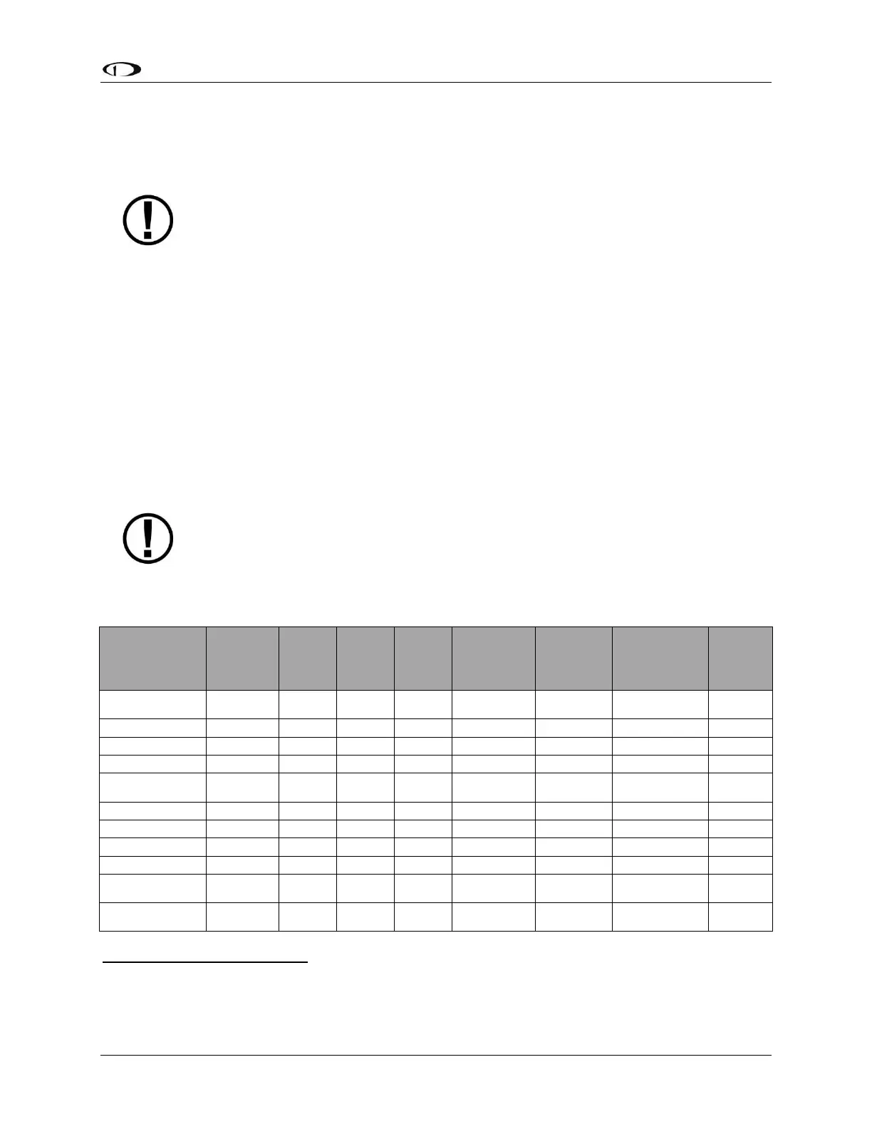
Table 8 outlines the functionality enabled by each source of data.
SkyView
SV-GPS-250
SV-GPS-
2020
ARINC-429
GPS via SV-
ARINC-429
3
ARINC-429 /
Serial (SL30)
NAV
4
SkyView
SV-ADAHRS-200
SV-ADAHRS-201
SkyView SE does not support SV-ARINC-429.
SkyView SE does not support external navigation devices.
Requires additional Aviation format serial input into SV-ARINC-429 module.
Approach-certified WAAS GPS units only.