SV-ADSB-470 Installation and Configuration
14-4 SkyView System Installation Guide - Revision AA
Select a position in the aircraft that is not too close to any high external heat source.
(The SV-ADSB-470 is not a significant heat source itself and does not need to be kept
away from other devices for this reason).
Avoid sharp bends and placing the cables too near to the aircraft control cables.
Secure the SV-ADSB-470 to the aircraft using its four (4) mounting holes. The device
should be mounted to a flat surface. The mounting tabs on each side of the module
have holes sized for #8-32 fasteners, but it is up to the installer to decide how the
module will be secured to the aircraft.
Additional items you will require, but which are not in the SV-ADSB-470 package, include:
SV-HARNESS-ADSB (or equivalent harness assembled by installer)
Antenna and fixing hardware. Antenna selection suggestions are available in the
following section.
Antenna cable and BNC Male connector. You need to supply and fabricate all required
antenna cables (or provided as part of your ADS-B antenna). Guidance on cable types is
given below.
Mounting hardware: To secure the SV-ADSB-470 to the aircraft.
Electrical Installation
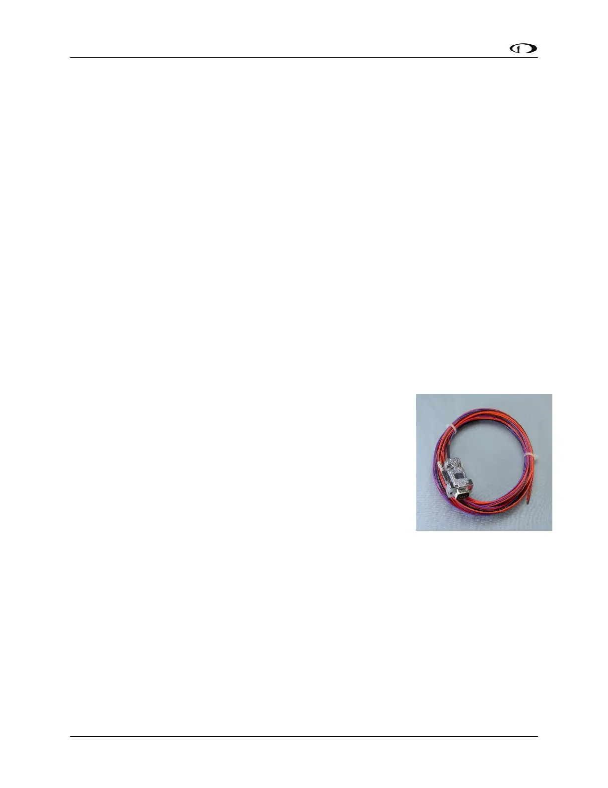
For connecting the SV-ADSB-470 to your SkyView system, Dynon
Avionics offers the optional SV-HARNESS-ADSB harness (pictured at
right). This harness is not included with the SV-ADSB-470. It comes
with 15 feet of wire, and the connector is pre-wired. If required, the
harness can be shortened, or lengthened (length is not critical).
Table 82 – SV-HARNESS-ADSB (below) reflects the wiring colors of
the SV-HARNESS-ADSB.
Additional harness construction and wiring information can be found
in Appendix C: Wiring and Electrical Connections.
The SV-ADSB-470 has a single D9F connector which provides the data
and power inputs to the module. A single BNC connector attaches to
the antenna.