SV-EMS-220/221 Installation and Configuration
SkyView System Installation Guide - Revision AA 7-49
2.0V relative to ground. If the peak voltage exceeds 50 volts, use the included 30 kΩ resistors as
described in the P-lead pickoff (Lycoming and Continental) Section above.
For signals that have a peak voltage of 12V or lower —such as Light Speed ignition outputs—
use the low voltage RPM inputs. These inputs require that the peak voltage goes at least 2.1
volts above ground, and crosses back down below 0.8V relative to ground to be counted as a
pulse.
For signals that have a peak voltage of 10-12V, either the Standard or Low Voltage RPM inputs
can be used.
Like the other methods above, you must know the number of pulses per revolution for your
RPM transducer.
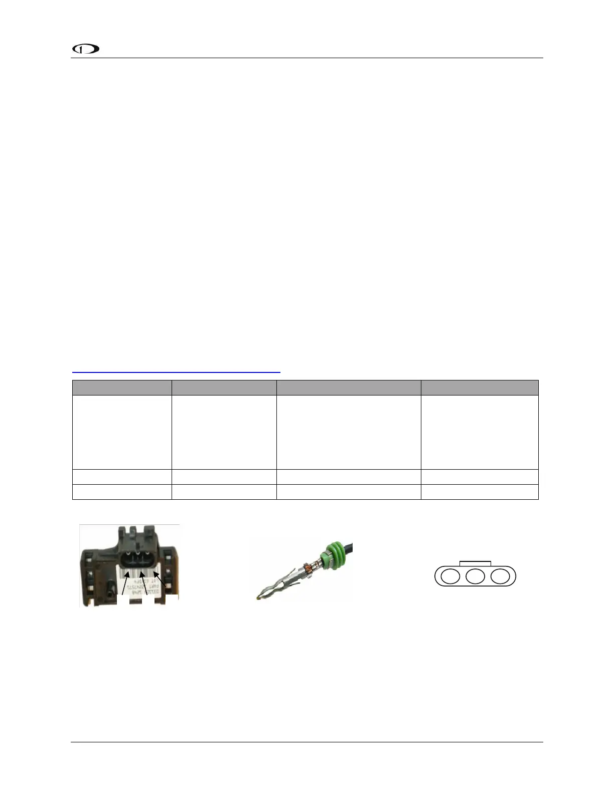
Manifold Pressure Sensor
The Dynon Avionics Manifold Pressure Sensor (P/N 100434-000) is an integral assembly
consisting of three pins, a rubber seal, and a connector housing. Strip 3/16” insulation off the
ends of the three wires listed at right. Slide the three rubber seals onto the three wires and the
pins onto the ends of the wires. Crimp the 3 included pins onto the ends of the wires, ensuring
that the long tabs that cradle the rubber seal wrap around the seal (see picture at right for
example). For more details on preparing and crimping the Weather Pack pins, see
http://www.whiteproducts.net/faqs.shtml.
Note that you may need access to the SV-EMS-220/221’s +5 Volts auxiliary supply for other
sensor installations, so make allowances for breaking out the connection to other areas. Route
the three wires to the location where you would like to mount the manifold pressure sensor.