SV-GPS-250/2020 GPS Receiver Installation and Configuration
8-4 SkyView System Installation Guide - Revision AA
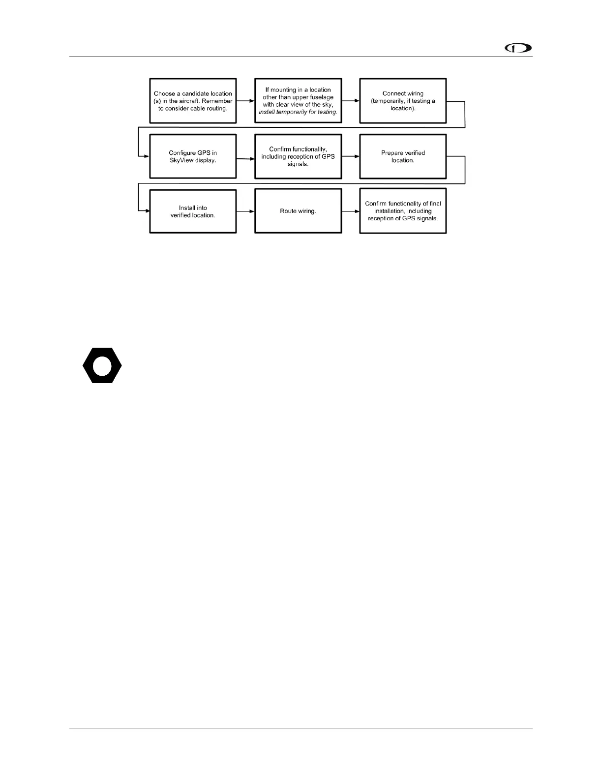
Figure 91 – Suggested SV-GPS-250/2020 Installation and Configuration Procedure
Physical Installation
Like all GPS devices, for most reliable performance, the SV-GPS-250/SV-GPS-2020
require a clear, unobstructed “view” of the sky. The SV-GPS-250/SV-GPS-2020 are
designed to be mounted on the upper fuselage of the aircraft for an unobstructed
(360° view) of the sky during maneuvers. If the SV-GPS-250/SV-GPS-2020 is
mounted inside the fuselage (for example, on the top of the panel or underneath a
cowling), the SV-GPS-250/2020’s view of the sky is partially or fully obstructed and
GPS performance may be marginal in situations such as insufficient number of
satellites “in view”.
Observe the following guidelines when choosing a location for an SV-GPS-250/2020:
The optimal location for the SV-GPS-250/2020 is a rigid surface on the upper fuselage of the
aircraft.
Mounting location should be relatively level (the base of the SV-GPS-250/2020 is flat).
Do not locate the receiver within 3 feet of transmitting antennas.
Avoid antenna shadows (i.e., obstructions that block the antenna’s view of the sky).
All four of the SV-GPS-250/2020’s wires should all be connected to each SkyView system
display for redundancy.
The diagram below shows the mounting dimensions of the SV-GPS-250/2020. Note that it
utilizes a common bolt pattern found in much of general aviation.