SV-EMS-220/221 Installation and Configuration
SkyView System Installation Guide - Revision AA 7-59
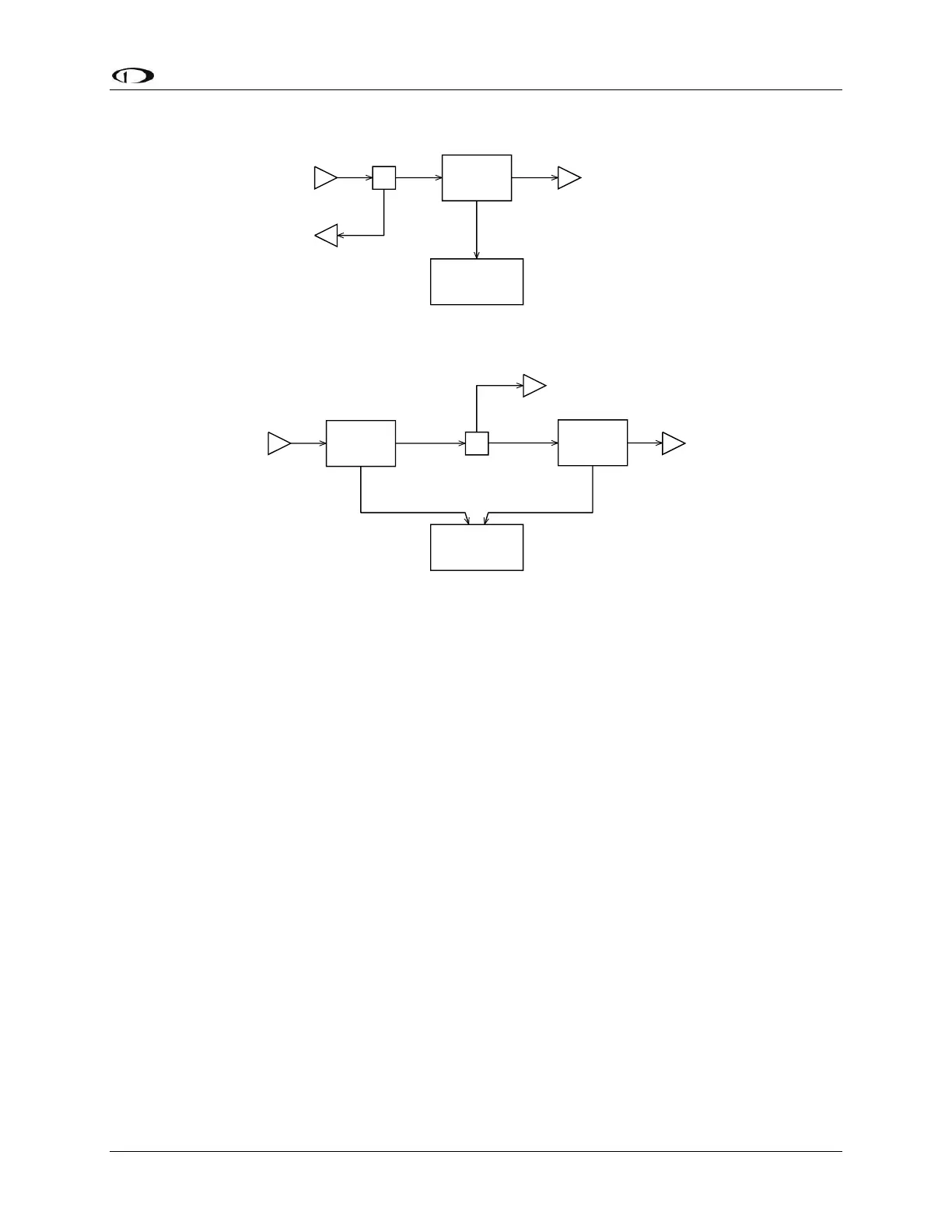
Figure 73 – Rotax Fuel Flow Transducers (Single-ended Measurement on Top
and Differential Measurement on Bottom)
In the differential fuel flow configuration in the lower portion of Figure 73, the first fuel flow
transducer measures the fuel flow from the fuel tank. The second fuel flow transducer
measures the unused fuel flow that returns to the fuel tank. The SV-EMS-220/221 takes data
from both transducers and calculates net instantaneous burn rate.
Fuel Level Sensor
Dynon Avionics does not sell fuel level sensors.
Resistive Fuel Level Sensors
You may connect as many resistive fuel level sensors to the SV-EMS-220/221 to General
Purpose (GP) input – any of Pins 4, 7, 9, 10, 11, 12, 20, 21 (that are not already in use). We
recommend not using Pins 6, 8, 22, and 23, and 31 for fuel level sensors as these pins are used
for some specialized functions. We recommend that Pins 20 and 21 of the SV-EMS-220/221 D37
be used for fuel level sensors before using other general purpose inputs.
If you use a General Purpose Input other than Pins 20 and 21, you must configure the pin you
use:
SETUP MENU > EMS SETUP > SENSOR INPUT MAPPING > C37 Pxx.
In SkyView Software v13.0, with SkyView Sensor Definition File Revision 46371 dated 2015-07-
16, you can choose the following options under SENSOR: