Appendix C: Wiring and Electrical Connections
23-6 SkyView System Installation Guide - Revision AA
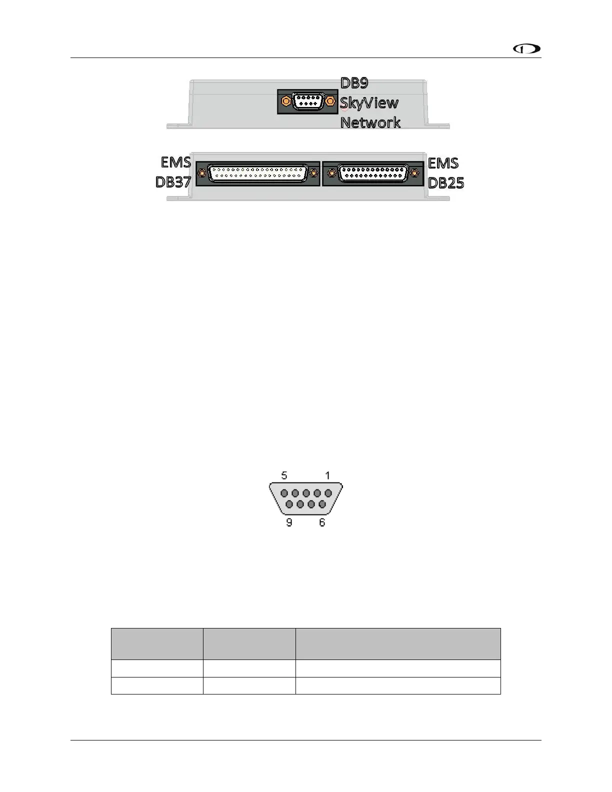
Figure 214 – SV-EMS-220/221 Connectors
The SV-GPS-2020 and SV-GPS-250 GPS receivers include four unterminated wires. These wires
may be trimmed or spliced and extended as needed to suit the installation location. Match the
colors of these wires with the corresponding colors on the display harness as mentioned in the
Serial Data Connection Section of SV-GPS-250/2020 GPS Receiver Installation and
Configuration.
The SV-BAT-320 has one connector. Do not add more wire into the SV-BAT-320 wire bundle.
Each SkyView servo has seven unterminated wires. Reference the AP Servo Installation,
Configuration, and Calibration section for more information.
SkyView Equipment Electrical Connector Pinout Tables
See tables on the follow pages for connector pin function descriptions. Tables for the USB jacks,
RJ45 jack, OAT connector, and battery connector are not included.
Servo Pinout (SV-NET-SERVO)
Figure 215 – SV-NET-SERVO D9F Connector Pin Numbering
Dynon Avionics servos (SV32, SV42, SV52, etc.) use a D9M connector (included with the SV-NET-
SERVO harness). Figure 215 – SV-NET-SERVO D9F Connector Pin Numbering above shows the
pin numbering for the servo’s D9M connector, from the rear (pin insertion) view.