Appendix C: Wiring and Electrical Connections
23-22 SkyView System Installation Guide - Revision AA
SV-COM-T8 Pinout
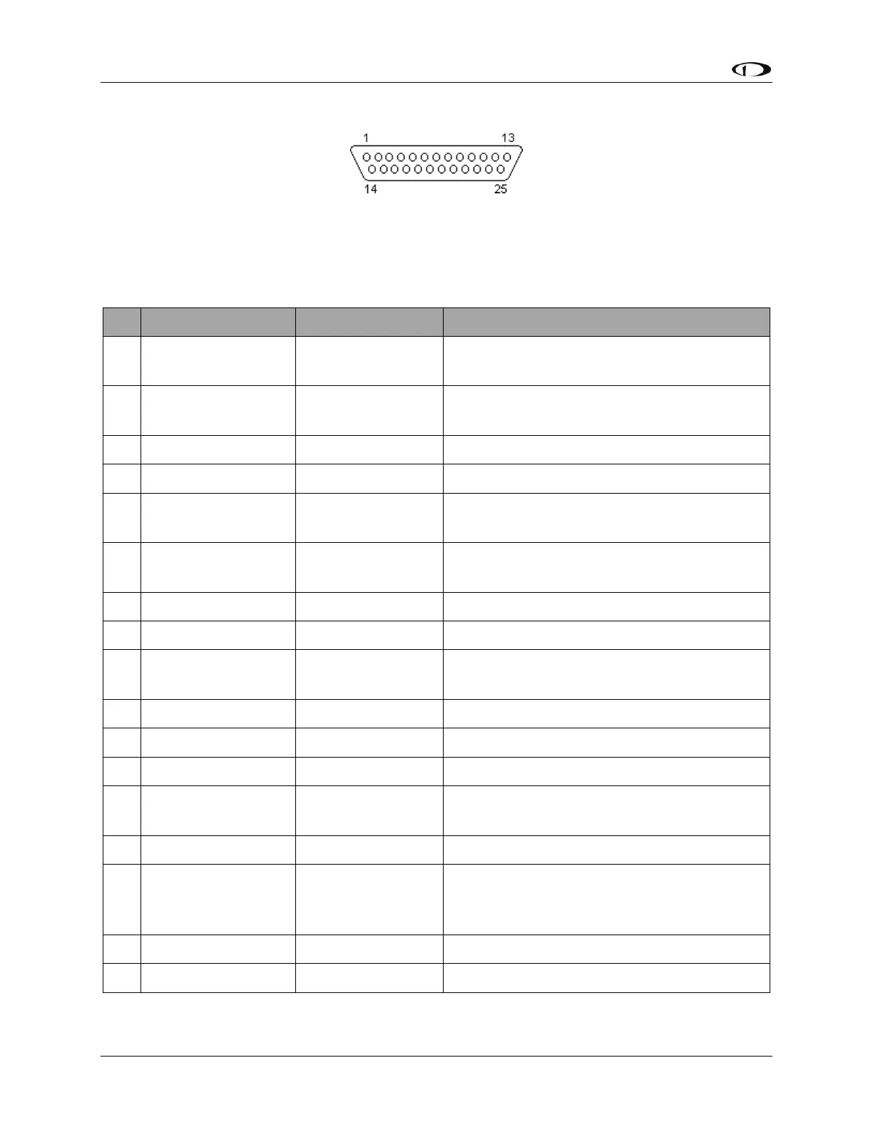
Figure 227 – SV-COM-T8 D25F Connector Pin Numbering
The SV-COM-T8 uses a D25M connector for connecting to the SV-COM-PANEL. Figure 227
above shows the pin numbering for the mating D25F connector, installed on the cable that
plugs into this connector, from the rear (pin insertion) view.
(determined by installer)
Connect to SV-INTERCOM-2S Pin 1
(inside shielded cable)
(determined by installer)
Connect to SV-INTERCOM-2S Pin 14
(inside shielded cable)
(determined by installer)
DATA RX FROM
SV-COM-PANEL
Connect to SV-COM-PANEL Pin 5
(determined by installer)
Connect to SV-COM-PANEL Pin 4
(determined by installer)
Connect to SV-INTERCOM-2S Pin 1
(determined by installer)
(determined by installer)
Connect to SV-COM-PANEL Pin 6
(determined by installer)
Connect to SV-INTERCOM-2S Pin 12 or Push
Button Normally Open (PBNO) to Ground
(Pin 9)