SV-ADSB-470 Installation and Configuration
SkyView System Installation Guide - Revision AA 14-9
Avoid kinking the cable even temporarily during installation.
Secure the cable so that it cannot interfere with other systems.
Antenna BNC Female Connector
This section describes the technique for attaching the antenna cable to a BNC Male connector.
A BNC Male connector is not supplied with the SV-ADSB-470. The SV-ADSB-470 has a BNC
Female connection. Therefore, you will need to source a BNC Male connector that is compatible
with the antenna cable type that meets your aircraft’s needs.
A dual crimp style BNC connector can be completed using a wide range of commercial crimp
tools (for example the Tyco 5-1814800-3). The die apertures for the inner pin and the outer
shield should be approximately 1.72 mm and 5.41 mm respectively.
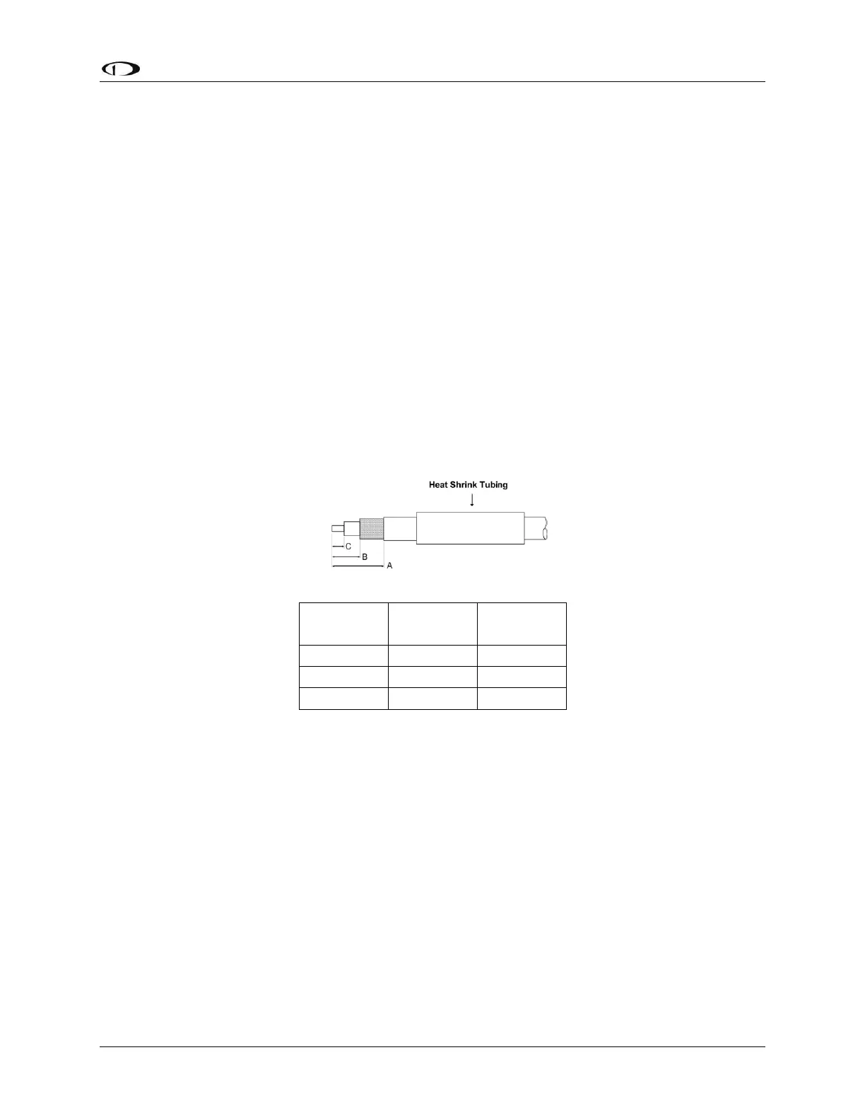
Strip back the coax cable to the dimensions in the table, as shown in the diagram below.
Slide 25 mm (1 inch) of heat shrink tubing over the cable.
Slide the outer crimp sleeve over the cable – it must go on before securing the center
contact.
Crimp the center contact to the cable.
Insert the cable into the connector – the center contact should click into place in the
body, the inner shield should be inside the body of the connector and the outer shield
should be outside the body.
Crimp the outer sleeve over the shield.
Slide heat shrink tubing forward (flush to connector) and heat to shrink the tubing.
SV-ADSB-470-Related SkyView Display Settings
Before the ADS-B STATUS menu can be accessed, the SV-ADSB-470 needs to be configured on
the SkyView system: