SV-ADSB-470 Installation and Configuration
SkyView System Installation Guide - Revision AA 14-5
SV-HARNESS-ADSB – Pinout (D9F on module / D9M on harness)
Connect to Aircraft Power
Data Input from SkyView Display(s):
Serial 1 – Pin 4 (Brown / Orange), or
Serial 2 – Pin 6 (Yellow / Orange), or
Serial 3 – Pin 8 (Green / Orange), or
Serial 4 – Pin 10 (Blue / Orange)
Data Output to SkyView Display(s):
Serial 1 – Pin 3 (Brown / Violet), or
Serial 2 – Pin 5 (Yellow / Violet), or
Serial 3 – Pin 7 (Green / Violet), or
Serial 4 – Pin 9 (Blue / Violet)
Connect to Aircraft Ground
Table 82 – SV-HARNESS-ADSB Wiring
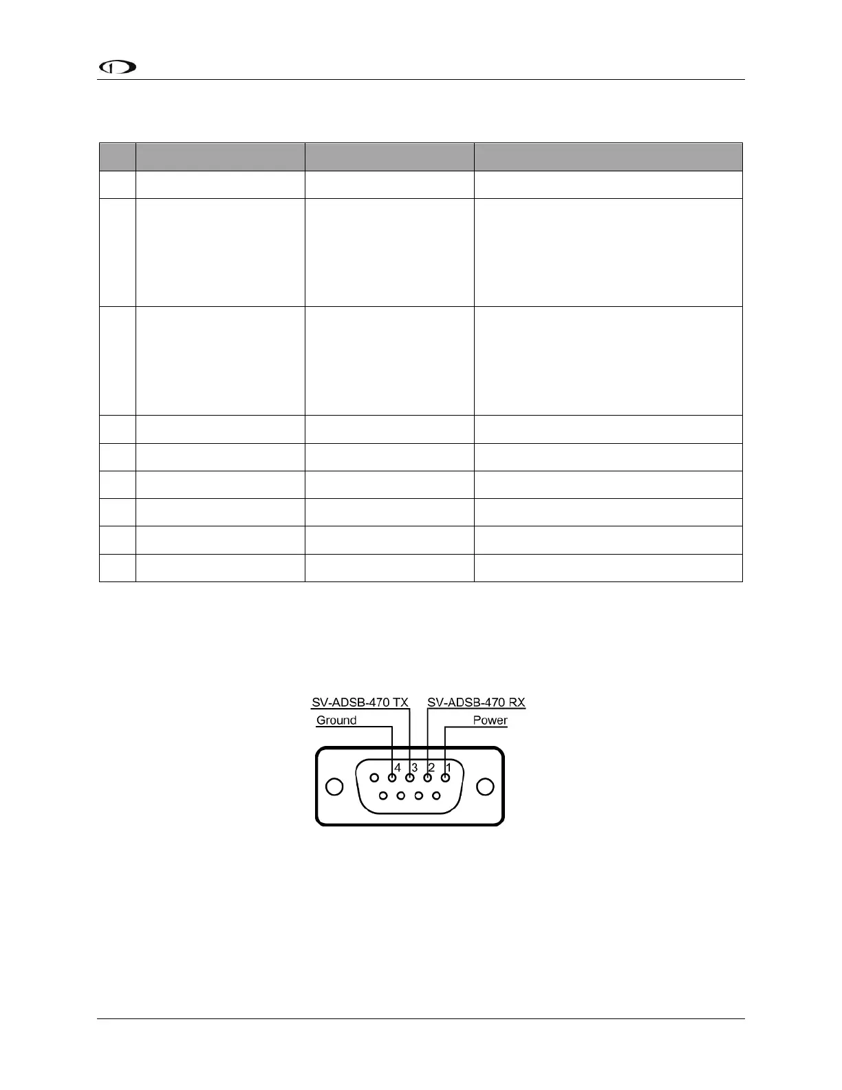
The pin out depicted in Figure 160 below depicts the view from the rear of your D9M connector
– the view you will have of your harness connector as you are inserting pins into the harness.
Note that the pin numbers are labelled on the face of both the female and male connector.
Figure 160 – SV-ADSB-470 Connector Diagram (From Rear of D9M Connector on the SV-ADSB-HARNESS)
The following table shows the connections for each of SkyView’s nominally available serial ports
(serial port 5 is usually used for connection to the SV-GPS-250/2020 module). Only ONE of the
following serial ports will be used: