Note, that in Figure 8, each SV-GPS-250/2020’s power, ground, and output wires
are connected to both displays on different serial ports. The primary SV-GPS-
250/2020 should be connected to serial port 5 on each display. The secondary SV-
GPS-250/2020 should be connected on another serial port on each display.
Additionally, if there are both multiple displays and multiple SV-GPS-250/2020
units in the system, power for the secondary GPS should be sourced from the GPS
power wire on the second display – in other words, each SV-GPS-250/2020 should
receive power from a different display. Reference the SV-GPS-250/2020 GPS
Receiver Installation and Configuration Section for more information on this
configuration.
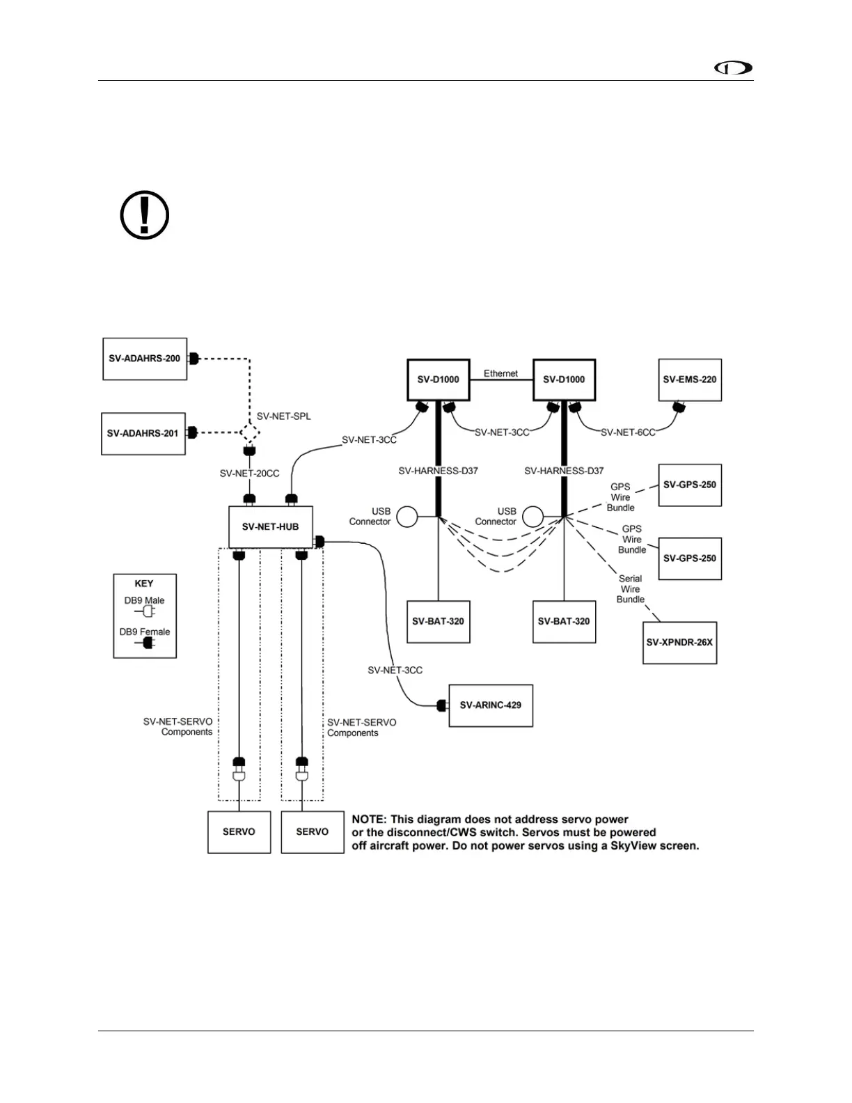
Figure 9 – SkyView System with Two Redundant Displays, One EMS, Two Backup Batteries (One per Display),
Two Redundant GPS, Two Redundant ADAHRS, Two Servos, and one Transponder using a hub (recommended
installation method)