EasyManua.ls Logo

Dynon Avionics SkyView Classic - Page 396

Default Icon
573 pages
Print Icon
To Next Page IconTo Next Page
To Previous Page IconTo Previous Page
Loading...
SV-COM-C25 Installation and Configuration
16-14 SkyView System Installation Guide - Revision AA
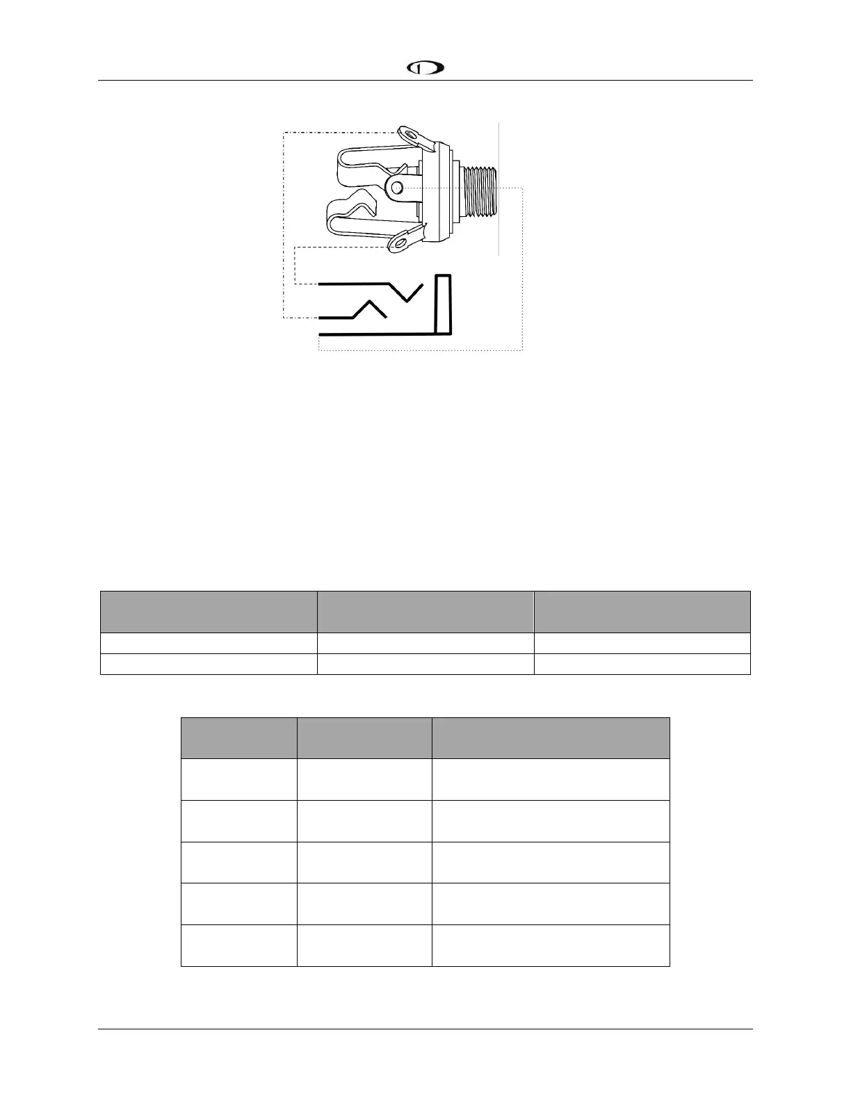
Figure 183 Headset Jack Schematic Interpretation
Power/Ground Input
The SV-COM-C25 requires 10-30V DC. For wire runs from power distribution to the SV-COM-
425 up to 6’, 22 AWG wire is sufficient for power and ground wires. For wire runs from power
distribution to the SV-COM-425 longer than 6’, 20 AWG wire is recommended for power and
ground wires. For the cable between the SV-COM-425 and the SV-COM-PANEL, 22 AWG power
and ground wire is sufficient. Use a 5 Amp fuse or circuit breaker for power supply protection to
each SV-COM-C25.
Power Specifications
Approximate current
consumption at 12 volts DC
Approximate current
consumption at 24 volts DC
SV-COM-C25 Transmit
3.0 Amps (average)
1.5 Amps (average)
SV-COM-C25 Receive
0.2 Amps (average)
0.1 Amps (average)
Table 91 SV-COM-C25 Power Consumption
SV-COM-425
Pin
SV-COM-PANEL
Pin
Notes
3
6
ENABLE
SV-COM-425 -> SV-COM-PANEL
7
1
POWER
SV-COM-425 -> SV-COM-PANEL
13
2
GROUND
SV-COM-425 -> SV-COM-PANEL
14
5
DATA OUT
SV-COM-PANEL -> SV-COM-425)
6
4
DATA IN
SV-COM-425 -> SV-COM-PANEL
Table 92 SV-COM-PANEL to SV-COM-425 Interconnections

Table of Contents

Related product manuals