SV-EMS-220/221 Installation and Configuration
7-80 SkyView System Installation Guide - Revision AA
2. Set the alarm. Scroll to the ALARM configuration line, move the joystick right to enter
the Alarm Adjust Menu, choose the appropriate alarm for the sensor, and then press
ACCEPT. Press BACK to return to the sensor configuration menu.
3. Set the graphical display limits. Scroll to the MAXIMUM and MINIMUM GRAPHICAL
DISPLAY lines, move the joystick right to enter the respective menus, adjust the values
appropriately - and then press ACCEPT. Press BACK to return to the sensor configuration
menu.
4. Set the ranges. Scroll the menu and configure enable, color, and top and bottom.
5. Save the settings. Press BACK to return to the Sensor Setup Menu. Press EXIT to return
to the Main Menu.
The examples on the following pages show four configured sensors: a voltmeter, a contact,
RPM, and an oil temperature sensor.
Example Voltmeter Setup
Assume this sensor was mapped on the Sensor Input Mapping Wizard as:
Table 64 – Example Sensor Input Mapping for C37 P1
Now, we want to configure its alert and graphical properties. Go to the Sensor Setup Menu and
open the MAIN VOLTS Page (SETUP MENU > EMS SETUP > SENSOR SETUP > MAIN VOLTS).
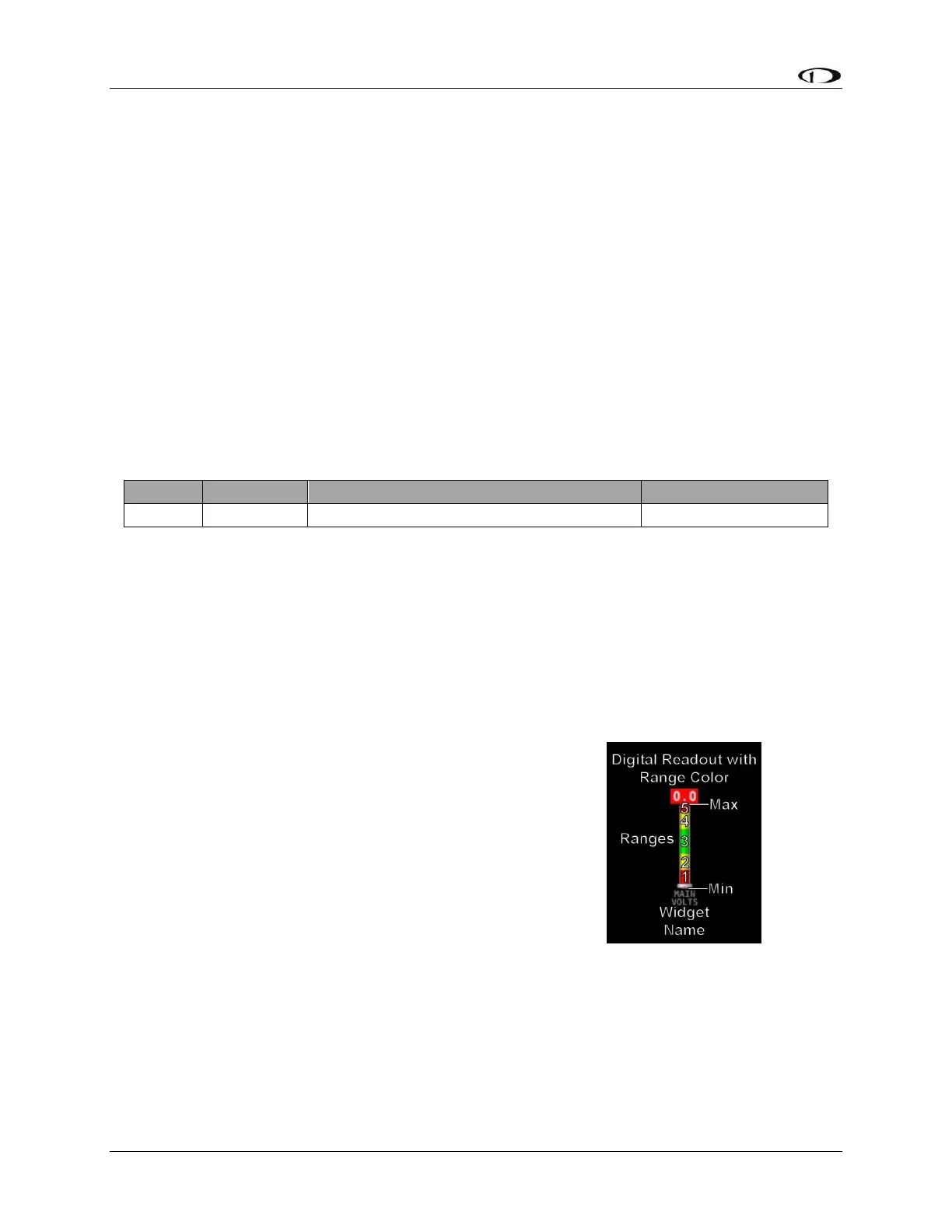
Configure MAIN VOLTS with the following properties:
ALARM: OFF
MAXIMUM GRAPHICAL DISPLAY: 15.0 VOLTS
MINIMUM GRAPHICAL DISPLAY: 10.0 VOLTS
SHOW SENSOR UNITS YES
RANGE 1
o ENABLE YES
o COLOR RED
o TOP 11.0 VOLTS
o BOTTOM 10.0 VOLTS
RANGE 2
o ENABLE YES
o COLOR YELLOW
o TOP 12.0 VOLTS
o BOTTOM 11.0 VOLTS
RANGE 3
o ENABLE YES
o COLOR GREEN
o TOP 13.6 VOLTS
o BOTTOM 12.0 VOLTS