SV-EMS-220/221 Installation and Configuration
7-82 SkyView System Installation Guide - Revision AA
o COLOR RED
o TOP 5.0 VOLTS
o BOTTOM 2.5 VOLTS
RANGE 2
o ENABLE YES
o NAME CLOSED
o COLOR GREEN
o TOP 2.5 VOLTS
o BOTTOM 0.0 VOLTS
RANGE 3
o ENABLE NO
o NAME R3
o COLOR GREEN
o TOP 20.0 VOLTS
o BOTTOM 10.0 VOLTS
RANGE 4
o ENABLE NO
o NAME R4
o COLOR YELLOW
o TOP 10.0 VOLTS
o BOTTOM 5.0 VOLTS
RANGE 5
o ENABLE NO
Example RPM Setup
Assume this sensor was mapped on the Sensor Input Mapping Wizard as:
Table 66 – Example Sensor Input Mapping for C37 P32/34 (RPM / Tachometer)
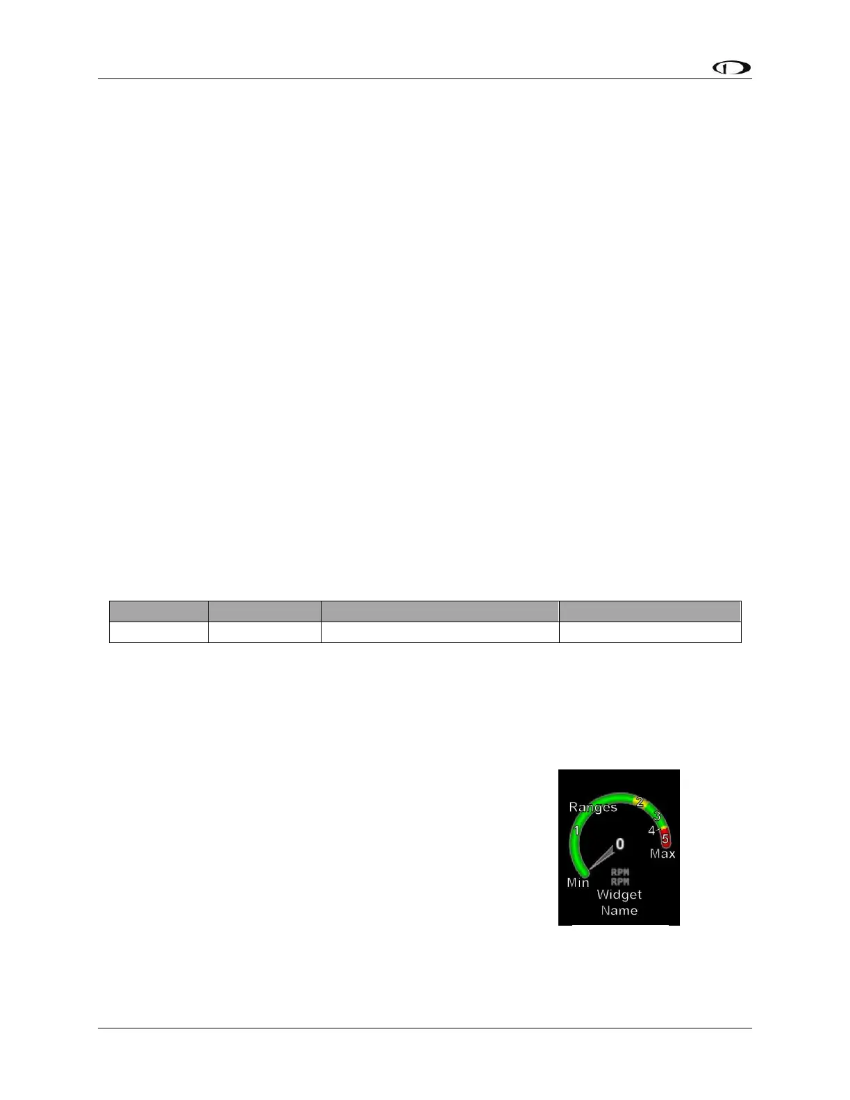
Now, we want to configure its alert and graphical properties. Go to the Sensor Setup Menu and
open the RPM Page (SETUP MENU > EMS SETUP > SENSOR SETUP > RPM RPM).
Configure RPM with the following properties:
ALARM: OFF
MAXIMUM GRAPHICAL DISPLAY: 3000 RPM
MINIMUM GRAPHICAL DISPLAY: 0 RPM
SHOW SENSOR UNITS YES
RANGE 1
o ENABLE YES
o COLOR GREEN
o TOP 2000 RPM
o BOTTOM 0 RPM
RANGE 2
o ENABLE YES