Partitioning 247
Codepad Connections For Partitioning - Examples
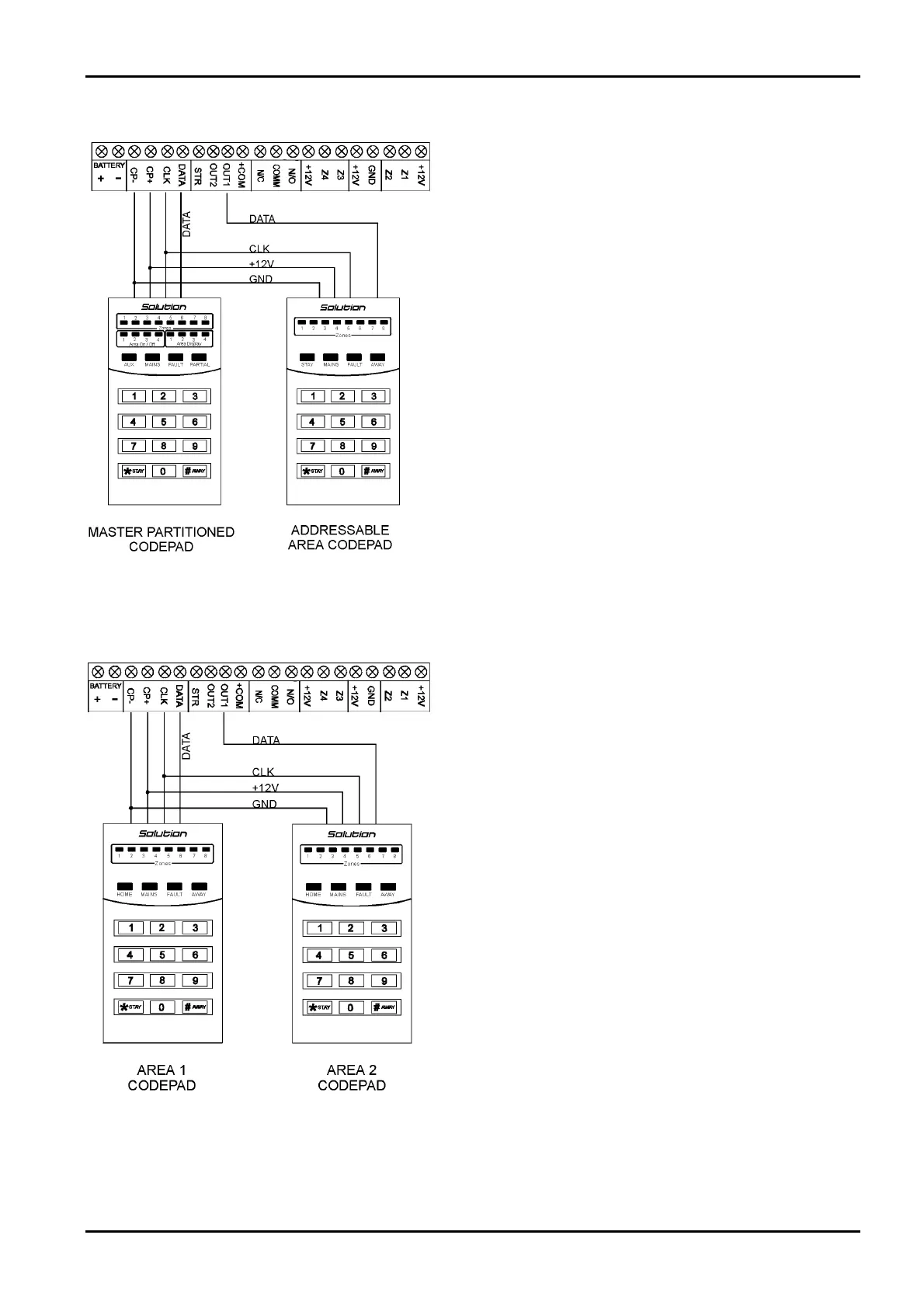
If the CP-5 Area Addressable (CP500A) codepad is assigned to
Area 1, DIP Switch 1 on the back of the remote codepad will need
to be in the ON position. The following locations for Output 1
will need to be programmed.
[LOCATION 380 = 6, 381 = 0]
If the CP-5 Area Addressable (CP500A) codepad is assigned to
Area 2, DIP Switch 2 on the back of the remote codepad will need
to be in the ON position. The following locations for Output 1
will need to be programmed.
[LOCATION 380 = 6, 381 = 1]
Figure 17: Connections For CP-5 Master Partitioned (CP500P)
Codepad and CP-5 Area Addressable (CP500A) Codepad
The following DIP Switch settings and locations must be
programmed for the two CP-5 Area Addressable (CP500A)
codepads to function correctly.
AREA 1 CODEPAD
DIP Switch 1 on the back of the remote codepad will need to be in
the ON position. The following location will also need to be
programmed.
[LOCATION 444, Option bit 2 must be enabled]
AREA 2 CODEPAD - (Output 1)
DIP Switch 2 on the back of the remote codepad will need to be in
the ON position. The following locations for Output 1 will need
to be programmed.
[LOCATION 380 = 6, 381 = 1]
Figure 18: Connections For Two CP-5 Eight Zone Area
Addressable (CP500A) Codepads
Electronics Design and Manufacturing Pty Limited ISSUE162.DOC