2/3
6. Electrical parts
66000
66000
Description of PCB (printer section)
• This PCB has connectors J219 (OUT), J220 (IN), J221 (OUT), J222 (IN), J223 (OUT) and J224 (IN) which are
connected to optical fiber cables. Be sure to read the Precautions in handling the cable before operation.
☞68100
!
!!
! Unused connector
!
!!
! Component parts table
*1. Cannot use the voltmeter.
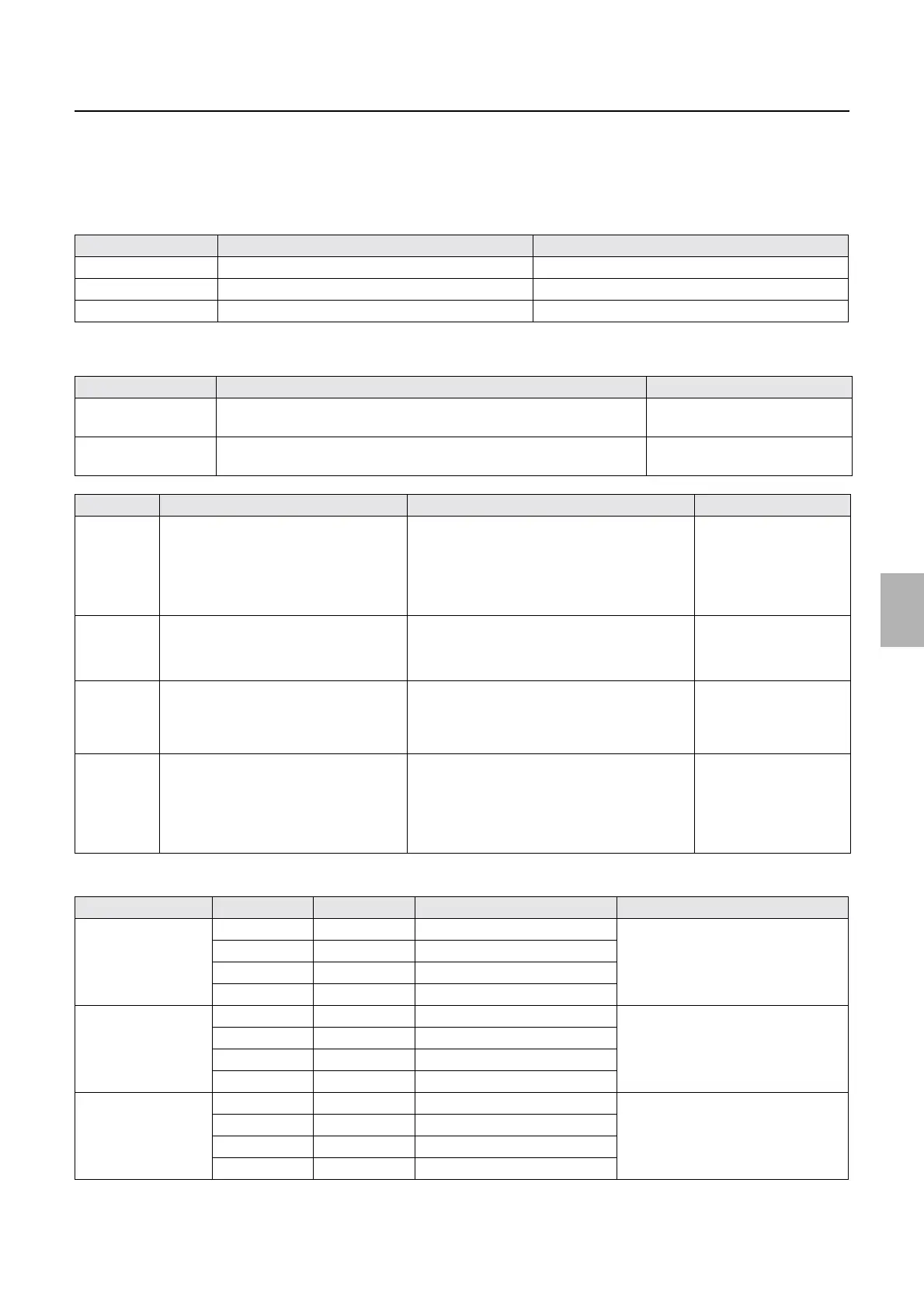
Connector No. Purpose Remarks
P210 Corresponds to the CVP. Option
P204 Quad magazine PCB, triple magazine PCB Option
P213 Quad magazine PCB Option
LED No. Purpose Status
LED1 DC+5 V input check On when the power supply is
turned on.
LED2 DC+3.3 V input check On when the power supply is
turned on.
TP Purpose When the normal value (# V) is not detected Symptom
TP1 DC+5 V voltage measurement
• Power supply for digital circuits such
as ARCNET, FPGA, memory, and
CPU
• TP1: not installed
• Failure in the cable connection between the
printer power supply 5 and printer control
PCB.
• Failure in the printer power supply 5 and
printer control PCB.
•
☞No. 06901
ARCNET
communication
error. occurs.
TP2 to TP6 Ground
• TP2: installed
• TP3 TP6: not installed
−−
TP7 DC+3.3 V voltage measurement
• TP7: not installed
• Failure in the printer control PCB •
☞No. 06901
ARCNET
communication
error. occurs.
TP8 to
TP15
*1
Unused
• Power supply for digital circuits such
as ARCNET, FPGA, memory, and
CPU
• TP8 to TP15: not installed
−−
Switch No. Bit No. Settings Purpose Remarks
DS1 1 OFF Unused Be sure to turn off.
2OFFUnused
3OFFUnused
4OFFUnused
DS2 1 OFF Unused Be sure to turn off.
2OFFUnused
3OFFUnused
4OFFUnused
DS3 1 OFF Unused Be sure to turn off.
2OFFUnused
3OFFUnused
4OFFUnused
Distributed by: minilablaser.com