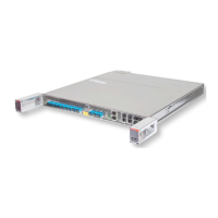
4.19
Install CD ROADM Cabling
Note: For each step in this procedure, verify that the dust cover has been removed from both the port and the
ber-opc cable. Verify that both the port and the ber-opc cable connectors are free of dust and other
contaminants before connecng the ber-opc cable.
Step 1
Connect the ber-opc cables from the transponder and/or the muxponder units to the appropriate client port
(C1…C16) on a 4x16 splier/coupler PIU.
Step 2
For add/drop connecons, connect the ber-opc cables from the appropriate edge ports (E1…E4) on a 4x16
splier/coupler PIU to the appropriate client port (C1…C9) on the 1x9 WSS ROB.
Step 3
For pass-through (hub) connecons, connect the ber-opc cables to the appropriate client ports (C1…C9) on
the 1x9 WSS ROB between the ROADM degrees.
✓ This task is complete.
Equipment Installation
Install CD ROADM Cabling
156
Release 19.1.1 · Issue 1.1, May 2021
Fujitsu and Fujitsu Customer Use Only