4.20
Install L160 Raman Cabling
This procedure describes how to connect the ber-opc cables between L100 ROB blade and L160 Raman blade.
Note: Follow the Raman cabling procedure when L160 Raman blade is used in the network.
Cauon: Raman blade must be powered down when connecng the ber-opc cables with L100 Blade.
Turn on the power supply only aer ensuring that the connecons are complete in all aspects and no open-
ended ber exists.
Danger: L160 Raman blade emits very HIGH power light.
Danger: Never look into any ports of Raman blade directly. Never look into the end of a ber, ber cord, or
ber pigtail connected with any ports of Raman blade. Permanent eye damage or blindness can occur
quickly when laser radiaon is present.
Danger: Never expose bare skin to light from E1 port of Raman blade. Never bring bare hands near the
surface of the connector of E1 port and near the ber which is connected with E1 port of Raman blade.
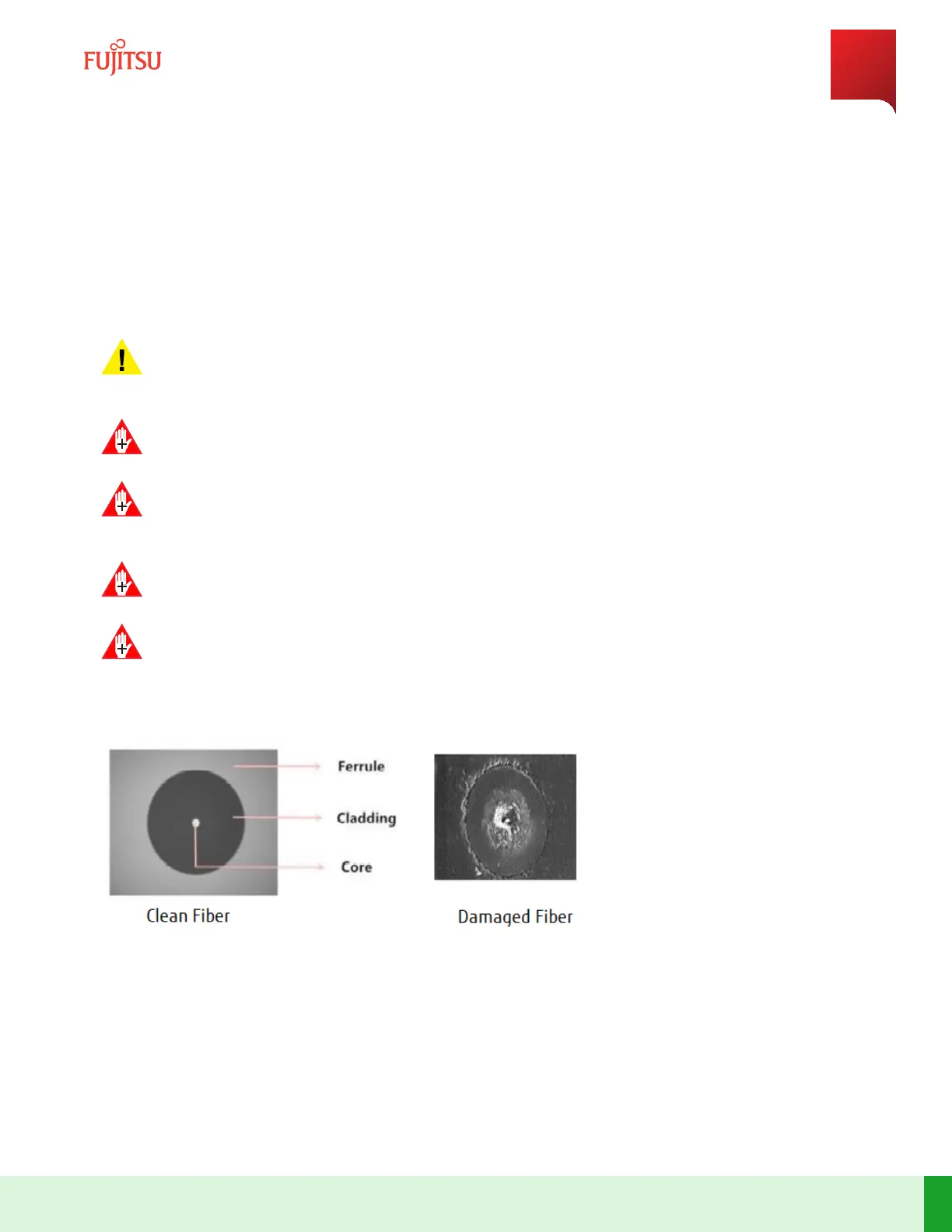
Danger: All ports and the surface of a ber connector should be cleaned thoroughly. If dust exists on the
surface of a ber connector or on the ports of Raman blade, it is burnt and melted due to the high power
light. The burning or melng acon causes damage to the ber connector or to the blade.
Figure 84
Clean and Damaged Fiber
Note: The ber from the network should be connected to E1 (RCV) port of the ROB through the Raman blade,
that is, the ber from the network (RCV) should be connected to E1 (RCV) port of the Raman blade. The C1
(TRMT) port of the Raman blade should be connected to E1 (RCV) port of the ROB.
Note: The E1 (TRMT) port of ROB connected to the ber, which is connected to the network, remains same for
both Raman and non-Raman conguraons.
Equipment Installation
Install L160 Raman Cabling
157
Release 19.1.1 · Issue 1.1, May 2021
Fujitsu and Fujitsu Customer Use Only