8.1
Trouble Clearing
In this secon:
8.1.1 L100 Blade LED Indicators
8.1.2 L110 Blade LED Indicators
8.1.3 L160 Blade LED Indicators
8.1.4 PIL1-3PS2 PIU LED Indicators
8.1.5 Retrieve Alarms and PMs
8.1.6 Alarms and Condions
8.1.7 Secondary Database Alarms and Events
8.1.8 LED Control
8.1.1
L100 Blade LED Indicators
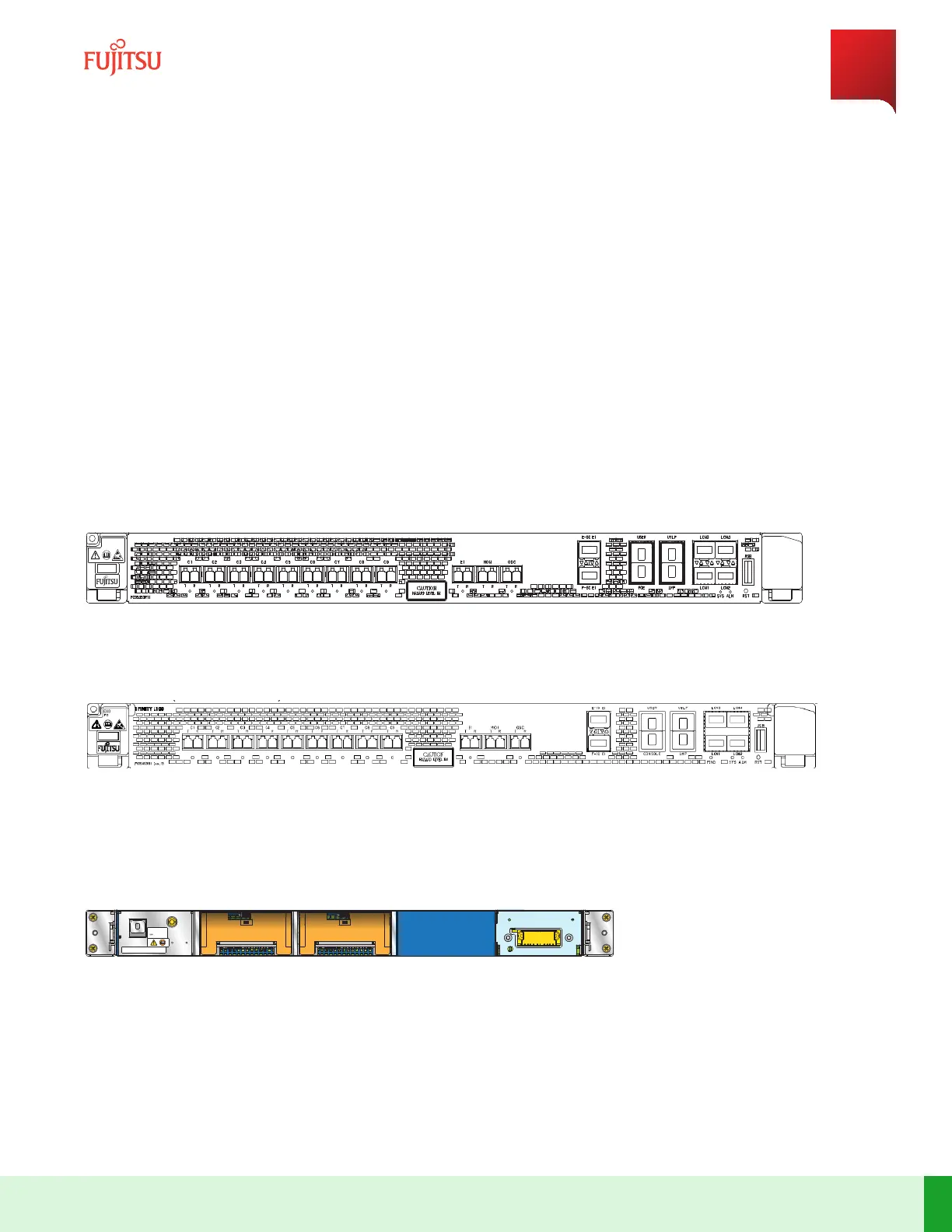
The following gures show front and rear views of the L100 Blade.
FG
ESD
1FINITY L100
FNC000975_Rev_02
Figure 101
Front View of L100 1x9 WSS ROB (Issue 13 and earlier)
Figure 102
Front View of L100 1x9 WSS ROB (Issue 14 and later)
Note: Issue 05 and earlier units have opcal port direcon labels O/I instead of T/R.
,10A
MAX,
FUSED
AT
15A
INPUT
RATING:
-40
TO
-57V
2
1
FAN
MAINT
FG
ESD
s8104ag_1
Figure 103
Rear View of L100 1x9 WSS ROB
Note: The Enty Type, E-SC-E1, and F-SC-E1 LED indicators are on the front of the SFP module installed in the
corresponding SFP cage. The FAN LED indicators are on the rear of the blade. All other LED indicators are on the
front of the blade.
System Maintenance
Trouble Clearing
284
Release 19.1.1 · Issue 1.1, May 2021
Fujitsu and Fujitsu Customer Use Only