above and below each other can cause the modules to snag during removal because of dierent
extracon lever designs and clearances.
Cauon: Do not remove the wrong ber connecons. Removing a ber connecon that is in use disrupts
service.
Step 1
Retrieve alarms.
Command:
> show alarms alarm-list
Step 2
Clear any alarms and standing condions currently being reported on the NE. Aer these alarms and standing
condions are cleared, connue with next step.
Step 3
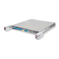
Obtain and inspect the replacement module for possible damage or debris. If necessary, record the serial and
issue numbers.
Step 4
Inspect the ber connecons to the module installed in the PIU. Verify that each ber is clearly marked or
labeled to idenfy the correct connecon locaon.
Step 5
Is each ber clearly marked to show its corresponding connector?
If YES:
Connue with next step.
If NO:
Mark or label bers according to local pracce and connue with the next step.
Step 6
Carefully and slowly press the LC connector tab on the ber-opc cable of a module to release and remove the
ber connectors from the module.
Cauon
: Do not remove the wrong ber connecons. Removing a ber connecon that is in use disrupts
service.
Step 7
Carefully grasp the latch and slowly remove the module from the PIU.
Step 8
Install temporary opcal connector covers into the opcal connectors on the module.
Step 9
Carefully install the replacement module into the same port of the PIU.
System Maintenance
Equipment Replacement
367
Release 19.1.1 · Issue 1.1, May 2021
Fujitsu and Fujitsu Customer Use Only