Upgrade and Maintenance Manual CX2550/60/70 M4
11.6.1 Preliminary steps . . . . . . . . . . . . . . . . . . . . . . . . 411
11.6.2 Removing the SXM2 riser (L) type 2 . . . . . . . . . . . . . . 411
11.6.3 Installing the SXM2 riser (L) type 2 . . . . . . . . . . . . . . . 412
11.6.4 Concluding steps . . . . . . . . . . . . . . . . . . . . . . . . 413
11.7 Replacing the SMX2 base board . . . . . . . . . . . . . . . 414
11.7.1 Preliminary steps . . . . . . . . . . . . . . . . . . . . . . . . 414
11.7.2 Removing the SXM2 base board . . . . . . . . . . . . . . . . 415
11.7.3 Installing the SXM2 base board . . . . . . . . . . . . . . . . . 416
11.7.4 Concluding steps . . . . . . . . . . . . . . . . . . . . . . . . 416
12 Cables . . . . . . . . . . . . . . . . . . . . . . . . . . . . . 419
12.1 Cabling overview . . . . . . . . . . . . . . . . . . . . . . . 420
12.2 Cabling . . . . . . . . . . . . . . . . . . . . . . . . . . . . . 421
12.3 Replacing the Omni-Path PHY card signal cable and
Omni-Path PHY card sideband cable . . . . . . . . . . . . 430
12.3.1 Preliminary steps . . . . . . . . . . . . . . . . . . . . . . . . 430
12.3.2 Removing the Omni-Path PHY card signal cable and the
Omni-Path PHY card sideband cable . . . . . . . . . . . . . . 431
12.3.2.1 Disconnecting the Omni-Path PHY card sideband cable
from the system board . . . . . . . . . . . . . . . . . . . 431
12.3.2.2 Disconnecting the Omni-Path PHY card signal cable
from the CPU type 2 . . . . . . . . . . . . . . . . . . . . . 432
12.3.2.3 Disconnecting the cables from the Omni-Path PHY card . . 434
12.3.3 Installing the Omni-Path PHY card signal cable and the
Omni-Path PHY card sideband cable . . . . . . . . . . . . . . 435
12.3.3.1 Connecting the cables to the Omni-Path PHY card . . . . . 435
12.3.3.2 Connecting the Omni-Path PHY card signal cable to the
CPU type 2 . . . . . . . . . . . . . . . . . . . . . . . . . 436
12.3.3.3 Connecting the Omni-Path PHY card sideband cable to the
system board . . . . . . . . . . . . . . . . . . . . . . . . 439
12.3.4 Concluding steps . . . . . . . . . . . . . . . . . . . . . . . . 440
13 Appendix . . . . . . . . . . . . . . . . . . . . . . . . . . . . 441
13.1 Mechanical overview . . . . . . . . . . . . . . . . . . . . . 441
13.1.1 Server node interior . . . . . . . . . . . . . . . . . . . . . . . 441
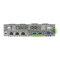
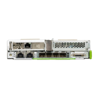
13.1.2 Server node rear . . . . . . . . . . . . . . . . . . . . . . . . 442
13.2 Connectors and indicators . . . . . . . . . . . . . . . . . . 443
 Loading...