CX2550/60/70 M4 Upgrade and Maintenance Manual 317
System board and components
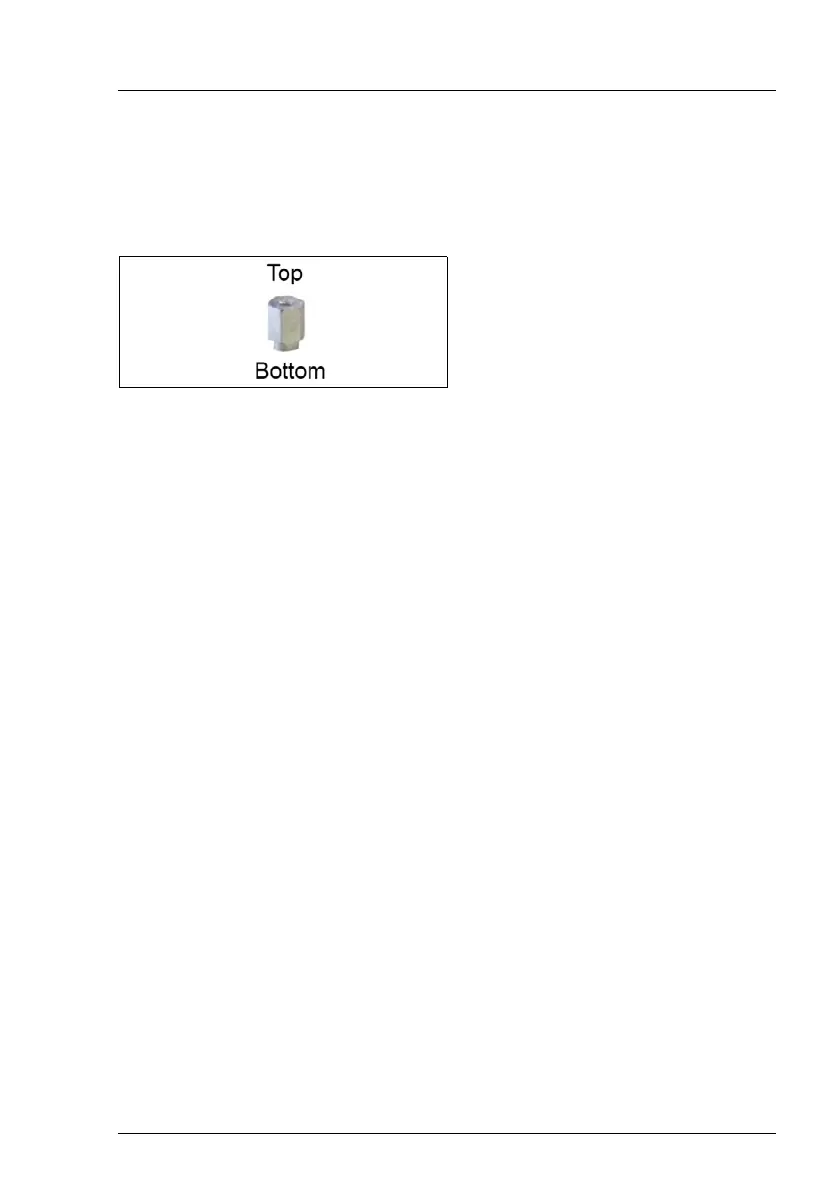
Ê Fix the stand-off for VR cooling blocks with 4 M2 screws from the back side
of the tray (2).
Use a hexagonal nut screw driver to secure the stud while fastening the
screw from the bottom of the tray.
9.6.2.4 Swapping CPUs
Preparing the CPU socket load plates on the new system board
Ê "Installing the CPU type 1" on page 213
Removing CPUs from the defective system board
Ê Carefully remove the CPUs from their sockets on the defective system
board, see "Removing the CPU type 1" on page 209.
V CAUTION!
Remove and reinstall one CPU at a time. Do not remove the second
CPU from the defective system board until the first CPU has been
installed on the new system board.
Installing CPUs on the new system board
Ê "Installing the CPU type 1" on page 213.
Installing protective socket covers on the defective system board
I Since the defective system board is sent back for repair, protect the
delicate CPU socket springs with a socket cover.
Ê "Installing the CPU type 1" on page 213
9.6.2.5 Completing the system board
Ê "Installing the M.2 SSD" on page 271 (if applicable)
Ê Fix the stand-offs on the system
board as shown.
 Loading...