Home
Fujitsu
Server
PRIMERGY CX2550 M4
Upgrade And Maintenance Manual
Page 219 (Installing the CPU Heat Sink)
Fujitsu PRIMERGY CX2550 M4 - Installing the CPU Heat Sink; CPU Heat Sink CPU1; CPU Heat Sink CPU2
454 pages
Manual
To Next Page
To Next Page
To Previous Page
To Previous Page
Loading...
CX2550/60/70
M4
Upgrade and Maintenance Manual
219
Processor (CPU)
8.2.7
Inst
alling the CPU heat s
ink
8.2.7.1
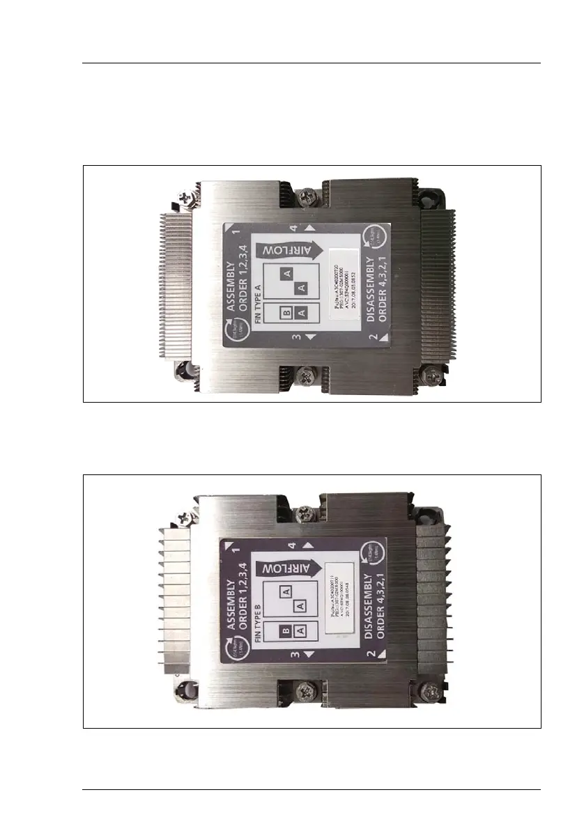
CPU heat sink CPU1
Figure 106: CPU heat sink for CPU1
8.2.7.2
CPU heat sink CPU2
Figure 107: CPU heat sink for CPU2
218
220
Table of Contents
Main Page
Default Chapter
2
Copyright and Trademarks
2
(CX2550 M4 / CX2560 M4) Type
2
Table of Contents
7
1 Introduction
21
Notational Conventions
22
2 Before You Start
23
Classification of Procedures
25
Customer Replaceable Units (CRU)
25
Upgrade and Repair Units (URU)
26
Field Replaceable Units (FRU)
27
Average Task Duration
28
Tools You Need at Hand
29
Documents You Need at Hand
30
Documents for the Server Node
31
Documents for the Server Enclosure
32
3 Important Information
33
Safety Instructions
33
Energy Star
41
CE Conformity
42
FCC Class a Compliance Statement
43
Environmental Protection
44
4 Basic Hardware Procedures
47
Using Diagnostics Information
47
Locating the Defective Server
47
Determining the Error Class
48
Customer Self Service (CSS) Indicator
48
Global Error Indicator
49
Locating the Defective Component
49
Local Diagnostic Indicators on the Front
49
Shutting down the Server Node
50
Removing the Server Node from the Server Enclosure
51
Removing the GPGPU / SXM2 Extension Tray
53
Installing the Riser Module
55
Removing the Riser Module
58
Installing the Dummy Riser Module
59
Removing the Dummy Riser Module
60
Mounting a Slot Cover to the Riser Module
61
Removing the Slot Cover from the Riser Module
61
Installing the OCP Dummy Module
62
Removing the OCP Dummy Module
62
Removing the Memory Slot Air Duct (Air Cooling Only)
63
Installing the Memory Slot Air Duct (Air Cooling Only)
64
Installing the GPGPU / SXM2 Extension Tray
65
Installing the Server Node in the Server Enclosure
67
Switching on the Server Node
69
Concluding Software Tasks
69
5 Basic Software Procedures
71
Starting the Maintenance Task
71
Suspending Bitlocker Functionality
71
Disabling the Boot Watchdog Functionality of Serverview Operations Manager
73
Viewing Boot Watchdog Settings
73
Configuring Boot Watchdog Settings
74
Removing Backup and Optical Disk Media
75
Verifying and Configuring the Backup Software Solution
75
Configuring LAN Teaming
75
Switching on the ID Indicator
76
Completing the Maintenance Task
77
Updating or Recovering the System Board BIOS and Irmc
77
Updating or Recovering the System Board BIOS
77
Updating or Recovering the Irmc
81
Verifying System Information Backup / Restore
83
Updating Expansion Card Firmware
83
Enabling Option ROM Scan
85
Resetting the Boot Retry Counter
86
Viewing the Boot Retry Counter
86
Enabling SVOM Boot Watchdog Functionality
88
Enabling Replaced Components in the BIOS
89
Reconfiguring the Backup Software Solution
90
Verifying the Memory Mode
90
Verifying the System Time Settings
92
Viewing and Clearing the System Event Log (SEL)
93
Viewing the SEL
93
Clearing the SEL
94
Updating the NIC Configuration File in a Linux and Vmware Environment
94
Resuming Bitlocker Functionality
96
Performing a RAID Array Rebuild
97
Looking up Changed MAC/WWN Addresses
97
Looking up MAC Addresses
98
Looking up WWN Addresses
98
Using the Chassis ID Prom Tool
99
Configuring LAN Teaming
100
After Replacing/Upgrading LAN Controllers
100
After Replacing a System Board
100
Switching off the ID Indicator
101
Performing a Fan Test
101
Resetting the Error Status after Replacing Cpus
103
Cpus
103
Updating Serverview RAID Manager
104
6 Expansion Cards and OCP Mezzanine Cards
105
Basic Information
106
Cx2550 M4
106
Cx2560 M4 / Cx2570 M4
110
Expansion Cards in the Riser Module
118
Installing Expansion Cards
119
Preliminary Steps
119
Mounting a Controller to the Riser Module
120
Connecting Cables to the Expansion Card
121
Concluding Steps
121
Removing Expansion Cards
122
Preliminary Steps
122
Removing a Controller from the Riser Module
123
Concluding Steps
123
Replacing Expansion Cards
124
Preliminary Steps
124
Removing an Expansion Card
124
Installing an Expansion Card
125
Connecting Cables to the Expansion Card
125
Concluding Steps
125
Expansion Cards in the SXM2 Riser Card (L) Type 2
127
Installing Expansion Cards
128
Preliminary Steps
128
Mounting an Expansion Card to SXM2 Riser Card (L) Type 2 . 129 6.3.1.3 Concluding Steps
130
Removing Expansion Cards
131
Preliminary Steps
131
Removing a Controller from the Riser Module
132
Concluding Steps
134
Replacing Expansion Cards
135
Preliminary Steps
135
Removing an Expansion Card
135
Installing an Expansion Card
136
Connecting Cables to the Expansion Card
136
Concluding Steps
136
Backup Unit
138
Basic Information
138
Installing the FBU
139
Preliminary Steps
140
Installing a TFM
140
Installing the FBU
143
Cabling of the FBU
146
Concluding Steps
148
Removing the FBU
149
Preliminary Steps
149
Removing the FBU
150
Concluding Steps
151
Replacing the FBU
152
Preliminary Steps
152
Removing the FBU
153
Installing the New FBU
153
Concluding Steps
153
Replacing the TFM
153
Preliminary Steps
153
Removing the TFM
154
Installing the New TFM
155
Concluding Steps
155
Riser Card
156
Replacing the Riser Card
156
Preliminary Steps
156
Replacing the Riser Card
157
Concluding Steps
157
OCP Mezzanine Cards
158
Installing OCP Mezzanine Cards
159
Preliminary Steps
159
Installing the OCP Mezzanine Card
160
Concluding Steps
160
Removing the OCP Mezzanine Card
161
Preliminary Steps
161
Removing the OCP Mezzanine Card
162
Concluding Steps
162
Replacing OCP Mezzanine Cards
163
Preliminary Steps
163
Removing the OCP Mezzanine Card
163
Installing an OCP Mezzanine Card
164
Concluding Steps
164
Additional Tasks
165
Mounting Expansion Card Slot Brackets
165
General Instructions
165
Network Adapter
166
Installing OCP Mezzanine Card Slot Brackets
168
General Instructions
168
OCP Mezzanine Card
169
Removing OCP Mezzanine Card Slot Brackets
171
Handling SFP+ Transceiver Modules
172
Installing SFP+ Transceiver Modules
172
Removing an SFP+ Transceiver Module
178
Replacing SFP+ Transceiver Modules
181
7 Main Memory
183
Basic Information
184
Memory Sequence
185
Overview of the DIMM Slots
186
Operation Modes
187
Installing Memory Modules
190
Preliminary Steps
190
Installing a Memory Module
191
Concluding Steps
193
Removing Memory Modules
194
Preliminary Steps
194
Removing a Memory Module
195
Concluding Step
196
Replacing Memory Modules
197
Preliminary Steps
197
Removing a Memory Module
198
Installing a Memory Module
198
Concluding Steps
198
Memory Module Cooling Pads for Liquid Cooling (LC)
198
Basic Information
198
Adhesive Rules for the Memory Cooling Pads
199
Replacing Memory Modules
201
Preliminary Steps
201
Preparing a Memory Module
201
Concluding Steps
203
8 Processor (CPU)
205
Basic Information
206
Supported Cpus
206
CPU Locations
206
Replacing CPU - Air Cooling
207
Preliminary Steps
207
Removing CPU Heat Sinks
208
Removing the CPU Heat Sinks
208
Removing the CPU Type 1
209
Removing the CPU Type 2
211
Installing the CPU Type 1
213
Installing the CPU Type 2
216
Installing the CPU Heat Sink
219
CPU Heat Sink CPU1
219
CPU Heat Sink CPU2
219
Installing the Heat Sinks
220
Concluding Steps
222
Replacing CPU - Liquid Cooling
223
Preliminary Steps
223
Removing the LC Heat Sinks
224
(CX2550 M4 / CX2560 M4) Type
226
CPU / RAM Loop Type 1: Removing the Flexible Tubes (CX2570 M4)
226
CX2550 M4 / CX2560 M4) Type 2
227
CPU / RAM Loop Type 1: Removing the Flexible Tubes (CX2570 M4)
229
Removing the Flexible Tubes of the CPU/RAM Loop Type 2
230
Removing the LC Heat Sinks
230
Removing the CPU Type 1
231
Removing the CPU Type 2
233
Installing the CPU Type 1
235
Installing the CPU Type 2
237
Installing the LC Heat Sinks
239
CPU / RAM Loop Type 1: Installing the Quick Connector Holder
248
(CX2550 M4 / CX2560 M4) Type
250
CPU / RAM Loop Type 1: Installing the Flexible Tubes (CX2570 M4)
250
CX2550 M4 / CX2560 M4) Type 2
252
CPU / RAM Loop Type 1: Installing the Flexible Tubes (CX2570 M4)
253
Installing the Flexible Tubes of the CPU/RAM Loop Type 2
254
Concluding Steps
256
Replacing the CPU Heat Sink
257
Preliminary Steps
257
Removing the CPU Heat Sink
257
Installing the CPU Heat Sink
257
Concluding Steps
258
Replacing the LC Heat Sinks
259
Preliminary Steps
259
Removing the LC Heat Sinks
259
Installing the LC Heat Sink
260
Concluding Steps
261
Applying Thermal Paste
262
9 System Board and Components
265
Replacing the CMOS Battery
265
Preliminary Steps
266
Localization of the CMOS Battery
267
Removing the CMOS Battery
268
Installing the CMOS Battery
269
Concluding Steps
270
Ssd
271
Installing the M.2 SSD
271
Preliminary Steps
271
Installing the M.2 SSD
272
Concluding Steps
274
Software Configuration
274
Removing the M.2 SSD
275
Preliminary Steps
275
Removing the M.2 SSD
276
Concluding Steps
276
Software Configuration
276
Replacing the M.2 SSD
278
Preliminary Steps
278
Removing the M.2 SSD
278
Re-Installing the M.2 SSD
279
Concluding Steps
279
Software Configuration
279
Trusted Platform Module (TPM) (no Information Available)
281
Installing the TPM
281
Installing the TPM
282
Concluding Steps
284
Removing the TPM
285
Preliminary Steps
286
Removing the TPM
287
Concluding Steps
289
Replacing the TPM
289
Preliminary Steps
290
Removing the Defective TPM
290
Installing the New TPM
290
Concluding Steps
290
Irmc Microsd Card
291
Installing the Irmc Microsd Card
291
Preliminary Steps
291
Installing the Irmc Microsd Card
292
Concluding Steps
293
Removing the Irmc Microsd Card
294
Preliminary Steps
294
Concluding Steps
295
Replacing the Irmc Microsd Card
296
Preliminary Steps
296
Concluding Steps
296
Dual Microsd 64GB Enterprise
297
Installing the Dual Microsd 64GB Enterprise
297
Preliminary Steps
297
Concluding Steps
299
Removing the Dual Microsd 64GB Enterprise
300
Preliminary Steps
300
Concluding Steps
301
Replacing the Dual Microsd 64GB Enterprise
301
Preliminary Steps
301
Concluding Steps
302
Replacing the Microsd Card
303
Preliminary Steps
303
Concluding Steps
304
Replacing the System Board
305
Preliminary Steps
307
Replacing the System Board
307
Preliminary Works: Server Node with Liquid Cooling
308
Removing the System Board
309
Installing the System Board
311
Swapping Cpus
317
Completing the System Board
317
Concluding Steps
318
10 GPGPU Extension Tray
321
Basic Information
322
Installing GPGPU Extension in Slot GPGPU 1
323
Preliminary Steps
323
Installing the GPGPU
324
Concluding Steps
328
Removing the GPGPU Extension from Slot GPGPU 1
328
Preliminary Steps
328
Removing the GPGPU
329
Concluding Steps
331
Replacing the GPGPU in Slot GPGPU 1
332
Preliminary Steps
332
Removing the GPGPU
332
Installing the GPGPU
333
Concluding Steps
334
Installing GPGPU Extension in Slot GPGPU 2
334
Preliminary Steps
334
Installing the GPGPU
335
Concluding Steps
337
Removing the GPGPU Extension from Slot GPGPU 2
338
Preliminary Steps
338
Removing the GPGPU
339
Concluding Steps
341
Replacing the GPGPU in Slot GPGPU 2
342
Preliminary Steps
342
Removing the GPGPU
342
Installing the GPGPU
343
Concluding Steps
344
Power Cables
345
Replacing the GPGPU Riser (R)
346
Preliminary Steps
346
Removing the GPGPU Riser
346
Installing the GPGPU Riser
347
Concluding Steps
347
Replacing the GPGPU Riser (L)
349
Preliminary Steps
349
Removing the GPGPU Riser
350
Cx2550/60/70 M4
351
Installing the GPGPU Riser
351
Concluding Steps
351
Replacing the Power Interface Board (PIB)
352
Preliminary Steps
352
Removing the PIB
352
Installing the PIB
354
Concluding Steps
355
11 SXM2 Extension Tray
357
Basic Information
358
Replacing SXM2 Modules
361
Preliminary Steps
361
Removing Liquid Cooling (LC)
361
Removing Liquid Cooling from SXM2 Modules 3 and 4
361
Removing Liquid Cooling from SXM2 Modules 1 and 2
369
Removing the SXM2 Module
377
Installing the SXM2 Module
378
Installing Liquid Cooling (LC)
379
Preparing the SXM2 Modules for LC
379
Installing Liquid Cooling for SXM2 Modules 1 and 2
379
Installing Liquid Cooling for SXM2 Modules 3 and 4
393
Concluding Steps
404
Replacing the SXM2 LC
405
Preliminary Steps
405
Concluding Steps
405
Replacing the SMX2 Riser (R)
407
Preliminary Steps
407
Removing the SXM2 Riser (R)
407
Installing the SXM2 Riser (R)
408
Concluding Steps
408
Replacing the SMX2 Riser (L) Type 1
409
Preliminary Steps
409
Removing the SXM2 Riser (L) Type 1
409
Installing the SXM2 Riser (L) Type 1
410
Concluding Steps
410
Replacing the SMX2 Riser (L) Type 2
411
Preliminary Steps
411
Removing the SXM2 Riser (L) Type 2
411
Installing the SXM2 Riser (L) Type 2
412
Concluding Steps
413
Replacing the SMX2 Base Board
414
Preliminary Steps
414
Removing the SXM2 Base Board
415
Installing the SXM2 Base Board
416
Concluding Steps
416
12 Cables
419
Cabling Overview
420
Cabling
421
Replacing the Omni-Path PHY Card Signal Cable and Omni-Path PHY Card Sideband Cable
430
Preliminary Steps
430
Removing the Omni-Path PHY Card Signal Cable and the Omni-Path PHY Card Sideband Cable
431
Disconnecting the Omni-Path PHY Card Sideband Cable from the System Board
431
Disconnecting the Omni-Path PHY Card Signal Cable from the CPU Type 2
432
Disconnecting the Cables from the Omni-Path PHY Card
434
Installing the Omni-Path PHY Card Signal Cable and the Omni-Path PHY Card Sideband Cable
435
Connecting the Cables to the Omni-Path PHY Card
435
Connecting the Omni-Path PHY Card Signal Cable to the
436
CPU Type 2
436
Connecting the Omni-Path PHY Card Sideband Cable to the
439
System Board
439
Concluding Steps
440
13 Appendix
441
Mechanical Overview
441
Server Node Interior
441
Server Node Rear
442
Connectors and Indicators
443
Cx2550/60/70 M4
443
System Board Connectors and Indicators
443
Onboard Connectors
443
Onboard Settings
446
Controls and Indicators on the Server Node
448
Control Elements
448
Indicators on the Server Node
449
LAN Indicators
450
Minimum Startup Configuration
452
Other manuals for Fujitsu PRIMERGY CX2550 M4
Operating Manual
70 pages
Disassembly And Recycling Document
76 pages
Related product manuals
Fujitsu PRIMERGY CX2550 M1
54 pages
Fujitsu PRIMERGY CX2560 M4
70 pages
PRIMERGY CX25 0 M4 Series
76 pages
Fujitsu PRIMERGY RX4770 M4
82 pages
Fujitsu PRIMERGY RX2540 M4
86 pages
Fujitsu PRIMERGY TX1330 M4
110 pages
Fujitsu PRIMERGY TX1320 M4
102 pages
Fujitsu PRIMERGY RX1330 M4
106 pages
Fujitsu PRIMERGY RX2520 M4
92 pages
Fujitsu PRIMERGY TX2550 M4
88 pages
Fujitsu PRIMERGY RX2530 M4
88 pages
PRIMERGY TX100 S3 Core Edition
90 pages