CX2550/60/70 M4 Upgrade and Maintenance Manual 441
13 Appendix
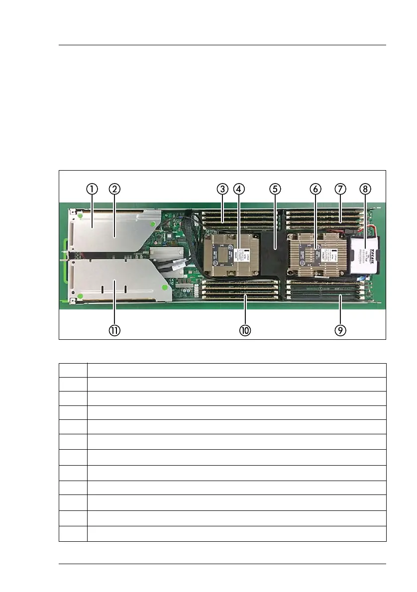
13.1 Mechanical overview
13.1.1 Server node interior
Figure 339: Example: PRIMERGY CX2560 M4 server node interior (with heat sinks)
Pos. Component
1 M.2 SSD (2x) (not visible, located under the riser module
2 Riser module on the left side
3 Memory slots for CPU1
4 CPU1 with heat sink
5
Memory air duct
6
CPU2 with heat sink
7
Memory slots for CPU2
8FBU
9
Memory slots for CPU2
10
Memory slots for CPU1
12
Riser module at the right side
 Loading...