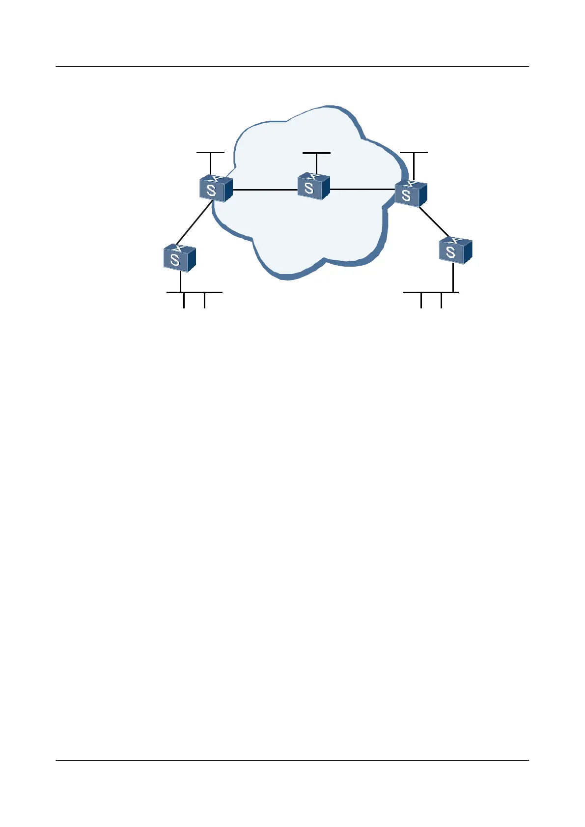
Figure 3-5 Networking diagram for configuring BGP ASN substitution
GE2/0/0
GE2/0/0
GE1/0/0
GE2/0/0
GE1/0/0
CE1
PE1 PE2
GE1/0/0
CE2
GE1/0/0
VPN1 VPN1
Loopback1
3.3.3.9/32
Loopback1
1.1.1.9/32
Loopback1
2.2.2.9/32
GE1/0/0
GE2/0/0
GE2/0/0
Backbone
AS 600 AS 600
AS 100
P
S9300 Interface VLANIF interface IP address
PE1 GigabitEthernet1/0/0 VLANIF 10 10.1.1.2/24
GigabitEthernet2/0/0 VLANIF 20 20.1.1.1/24
PE2 GigabitEthernet1/0/0 VLANIF 40 10.2.1.2/24
GigabitEthernet2/0/0 VLANIF 30 30.1.1.2/24
P GigabitEthernet1/0/0 VLANIF 20 20.1.1.2/24
GigabitEthernet2/0/0 VLANIF 30 30.1.1.1/24
CE1 GigabitEthernet1/0/0 VLANIF 10 10.1.1.1/24
GigabitEthernet2/0/0 VLANIF 50 100.1.1.1/24
CE2 GigabitEthernet1/0/0 VLANIF 40 10.2.1.1/24
GigabitEthernet2/0/0 VLANIF 60 200.1.1.1/24
Configuration Roadmap
The configuration roadmap is as follows:
1. Enable IGP on the backbone network to implement interworking between PEs, and between
PE and P so that they can learn loopback address of each other.
2. Create an MPLS LDP LSP between the PEs, create VPN instances on PEs, and connect
PEs to CEs.
3. Establish EBGP adjacencies between the PEs and CEs to import routes of the CEs to the
PEs.
3 BGP/MPLS IP VPN Configuration
Quidway S9300 Terabit Routing Switch
Configuration Guide - VPN
3-80 Huawei Proprietary and Confidential
Copyright © Huawei Technologies Co., Ltd.
Issue 03 (2009-08-20)

 Loading...


