interface GigabitEthernet2/0/0
port hybrid pvid vlan 20
port hybrif tagged vlan 20
#
#
ccc CE1-CE2 interface Vlanif 10 in-label 100 out-label 200 nexthop 10.1.1.2
#
interface LoopBack1
ip address 1.1.1.9 255.255.255.255
#
return
l Configuration file of CE2
#
sysname CE2
#
vlan batch 20
#
interface Vlanif20
ip address 30.1.1.2 255.255.255.0
#
interface GigabitEthernet1/0/0
port link-type trunk
port trunk allow-pass vlan 20
#
return
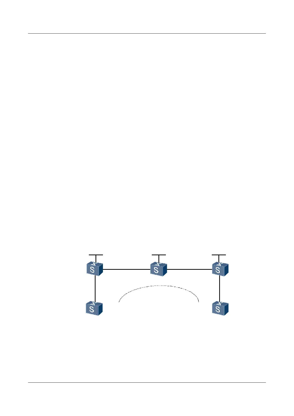
4.11.6 Example for Configuring a Remote Kompella Connection
Networking Requirements
As shown in Figure 4-9, CE1 and CE2 are respectively connected to PE1 and PE2 through GE
interfaces.
A remote Kompella VLL is set up between CE1 and CE2.
Figure 4-9 Networking diagram for configuring a remote Kompella VLL
GE 2/0/0
GE 1/0/0 GE 2/0/0
GE 1/0/0
GE 1/0/0
P PE 2
PE 1
CE 1
CE 2
GE 2/0/0
GE 1/0/0
GE 1/0/0
Loopback1
1.1.1.9/32
Loopback1
2.2.2.9/32
Loopback1
3.3.3.9/32
Kompella
Remote
S9300
Interface VLANIF interface IP address
PE1 GigabitEthernet1/0/0 VLANIF 10 -
GigabitEthernet2/0/0 VLANIF 20 168.1.1.1/24
Loopback1 - 1.1.1.9/32
PE2 GigabitEthernet1/0/0 VLANIF 30 169.1.1.2/24
4 VLL Configuration
Quidway S9300 Terabit Routing Switch
Configuration Guide - VPN
4-62 Huawei Proprietary and Confidential
Copyright © Huawei Technologies Co., Ltd.
Issue 03 (2009-08-20)

 Loading...


