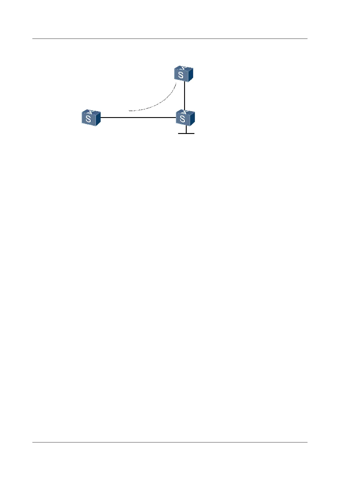
Figure 4-4 Networking diagram for configuring local CCC connection
CE 1
CE 2
PE
GE 1/0/0
GE1/0/0
GE 1/0/0
GE 2/0/0
CCC local connection
Loopback1
1.1.1.9/32
S9300 Interface VLANIF interface IP address
PE GigabitEthernet1/0/0 VLANIF 10 -
GigabitEthernet2/0/0 VLANIF 20 -
Loopback1 - 1.1.1.9/32
CE1 GigabitEthernet1/0/0 VLANIF 10 100.1.1.1/24
CE2 GigabitEthernet1/0/0 VLANIF 20 100.1.1.2/24
Configuration Roadmap
The configuration roadmap is as follows:
1. Configure the basic MPLS capacity on the PE and enable the MPLS L2VPN.
2. Create a local connection between CE1 and CE2 on PE. The local CCC connection is
bidirectional, so only one connection is needed.
Data Preparation
IP addresses of the interfaces
Procedure
Step 1 Configure CEs.
# Configure CE1.
<Quidway> system-view
[Quidway] sysname CE1
[CE1] vlan 10
[CE1-Vlan10] quit
[CE1]interface GigabitEthernet1/0/0
[CE1-GigabitEthernet1/0/0]port link-type trunk
[CE1-GigabitEthernet1/0/0]port trunk allow-pass vlan 10
[CE1-GigabitEthernet1/0/0]quit
[CE1] interface vlanif 10
[CE1-Vlanif10] ip address 100.1.1.1 24
[CE1-Vlanif10] quit
# Configure CE2.
Quidway S9300 Terabit Routing Switch
Configuration Guide - VPN 4 VLL Configuration
Issue 03 (2009-08-20) Huawei Proprietary and Confidential
Copyright © Huawei Technologies Co., Ltd.
4-37

 Loading...


