6.11.1 Example for Configuring Martini VPLS
Networking Requirements
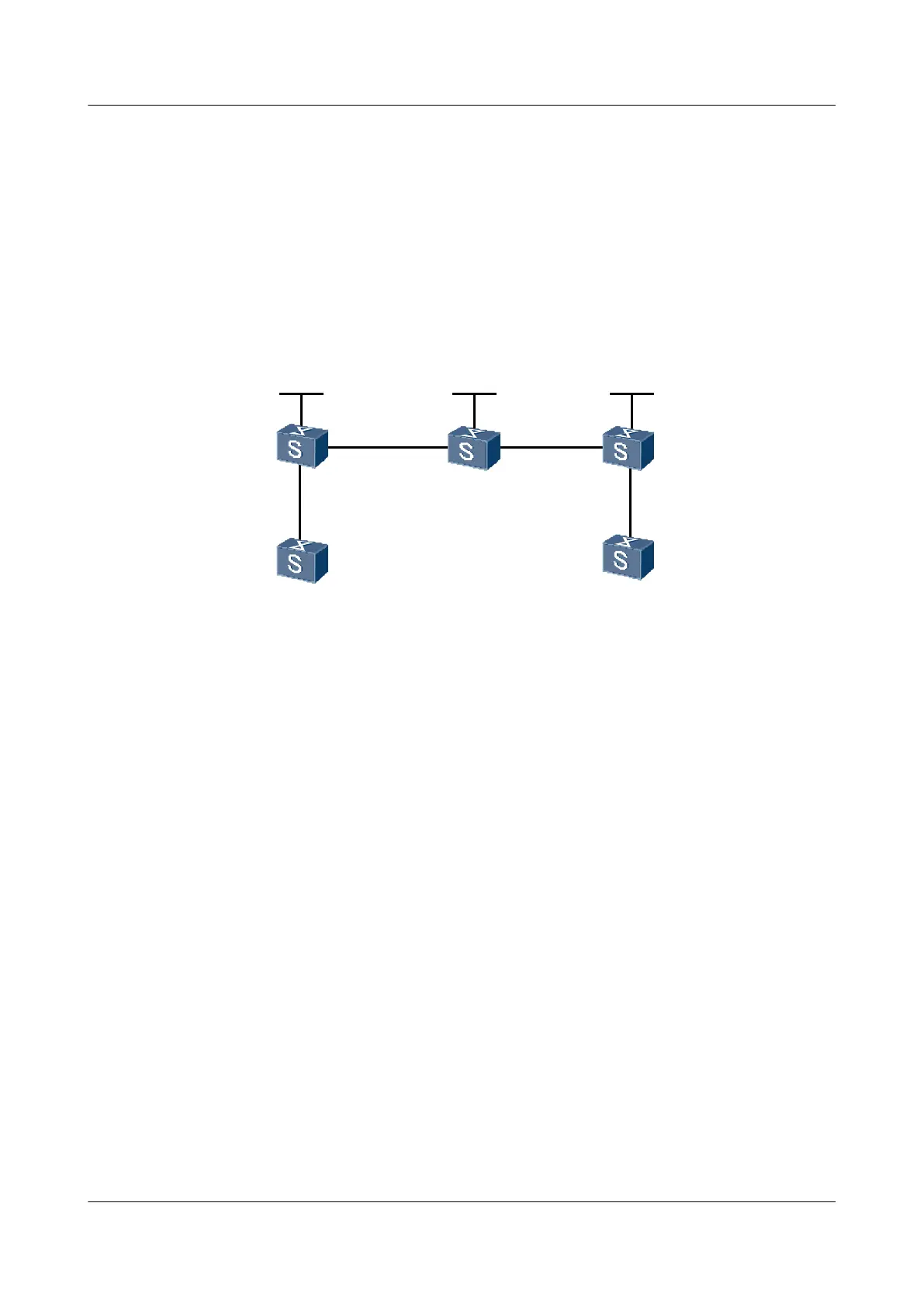
As shown in Figure 6-5, VPLS needs to be enabled on PE1 and PE2; CE1 is connected to PE1
and CE2 is connected to PE2; CE1 and CE2 belong to the same VPLS network; PWs are
established with LDP as the VPLS signaling, and VPLS is configured to implement the
interworking between CE1 and CE2.
Figure 6-5 Networking diagram for configuring Martini VPLS
CE1
CE2
PE1
PE2
P
Loopback1
1.1.1.9/32
Loopback1
2.2.2.9/32
Loopback1
3.3.3.9/32
GE2/0/0
GE1/0/0
GE2/0/0
GE1/0/0
GE1/0/0
GE2/0/0
GE1/0/0 GE1/0/0
S9300 Interface VLANIF Interface IP Address
PE1 GigabitEthernet 1/0/0 VLANIF 10 -
GigabitEthernet 2/0/0 VLANIF 20 168.1.1.1/24
Loopback1 - 1.1.1.9/32
PE2 GigabitEthernet 1/0/0 VLANIF 30 169.1.1.2/24
GigabitEthernet 2/0/0 VLANIF 40 -
Loopback1 - 3.3.3.9/32
P GigabitEthernet 1/0/0 VLANIF 20 168.1.1.2/24
GigabitEthernet 2/0/0 VLANIF 30 169.1.1.1/24
Loopback1 - 2.2.2.9/32
CE1 GigabitEthernet 1/0/0 VLANIF 10 10.1.1.1/24
CE2 GigabitEthernet 1/0/0 VLANIF 40 10.1.1.2/24
Configuration Roadmap
The configuration roadmap is as follows:
1. Configure a routing protocol on the backbone network to implement the interworking
between devices.
2. Establish remote LDP sessions between PEs.
6 VPLS Configuration
Quidway S9300 Terabit Routing Switch
Configuration Guide - VPN
6-38 Huawei Proprietary and Confidential
Copyright © Huawei Technologies Co., Ltd.
Issue 03 (2009-08-20)

 Loading...


