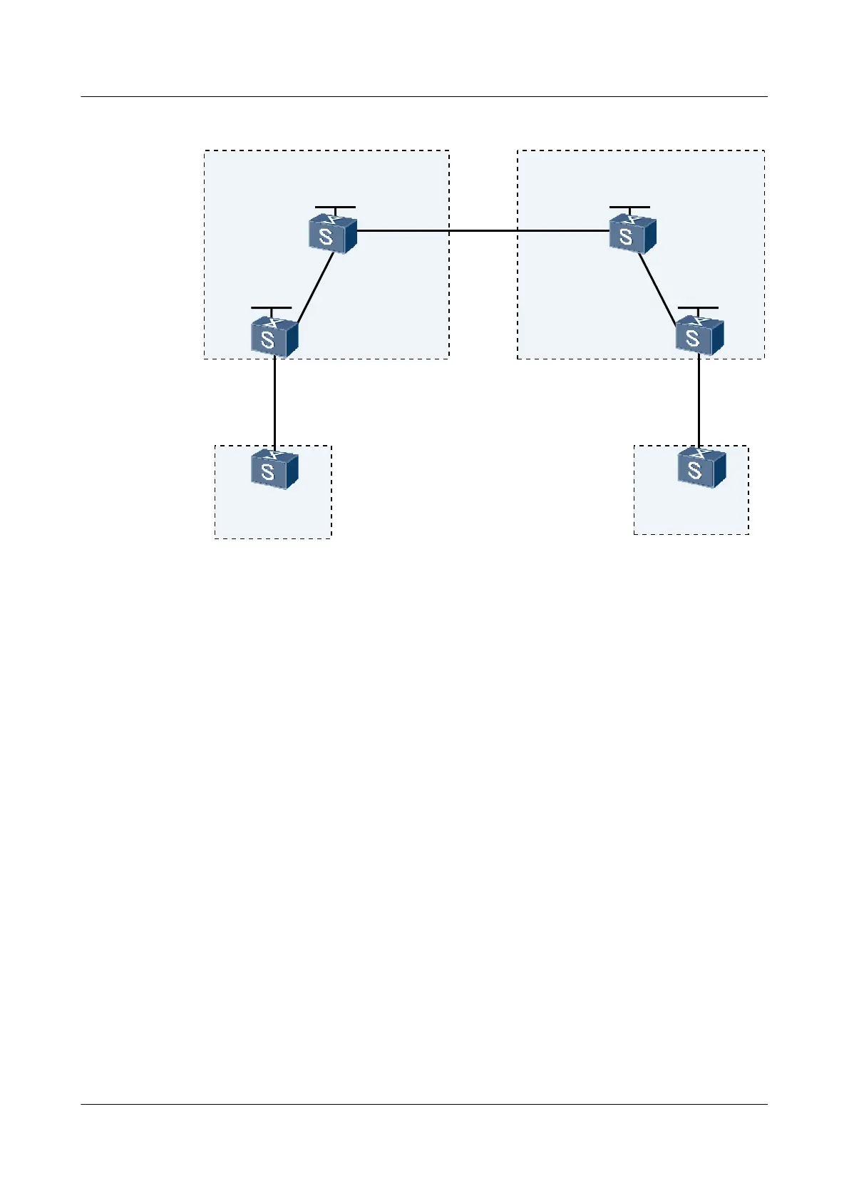
Figure 3-7 Networking diagram for configuring inter-AS VPN Option A
PE2
ASBR-PE2
BGP/MPLS Backbone
AS 200
ASBR-PE1
PE1
BGP/MPLS Backbone
AS 100
GE2/0/0
10.1.1.2/24
Loopback1
1.1.1.9/32
GE1/0/0
172.1.1.2/24
GE2/0/0
192.1.1.1/24
Loopback1
2.2.2.9/32
172.1.1.1/24
Loopback1
3.3.3.9/32
GE1/0/0
162.1.1.1/24
GE1/0/0
162.1.1.2/24
Loopback1
4.4.4.9/32
GE2/0/0
10.2.1.2/24
CE1
AS 65001
CE2
AS 65002
GE1/0/0
10.1.1.1/24
GE1/0/0
10.2.1.1/24
GE2/0/0
192.1.1.2/24
GE1/0/0
VLAN
10
VLAN
10
VLAN 11
VLAN 12
VLAN 22
Configuration Roadmap
The configuration roadmap is as follows:
1. Set up the EBGP peer relation between the PE and the CE and set up MP-IBGP peer relation
between the PE and the ASBR.
2. Create a VPN instance on the two ASBR-PEs and bind the VPN instance to the interface
connected to the other ASBR-PE (regarding the ASBR-PE as its CE) and set up the EBGP
peer relation between the ASBR-PEs.
Data Preparation
To complete the configuration, you need the following data:
l MPLS LSR IDs of PEs and ASBR-PEs
l VPN instance names, RDs, and VPN targets for the PEs and ABSR-PEs
Procedure
Step 1 Create VLANs and specify the VLAN IDs that are allowed by the interfaces, as shown in Figure
3-7.
The configuration procedure is not mentioned here.
Step 2 On the MPLS backbone networks in AS 100 and AS 200, configure an IGP protocol so that the
PEs and the ASBRs on the network can communicate with each other.
Quidway S9300 Terabit Routing Switch
Configuration Guide - VPN 3 BGP/MPLS IP VPN Configuration
Issue 03 (2009-08-20) Huawei Proprietary and Confidential
Copyright © Huawei Technologies Co., Ltd.
3-97

 Loading...


