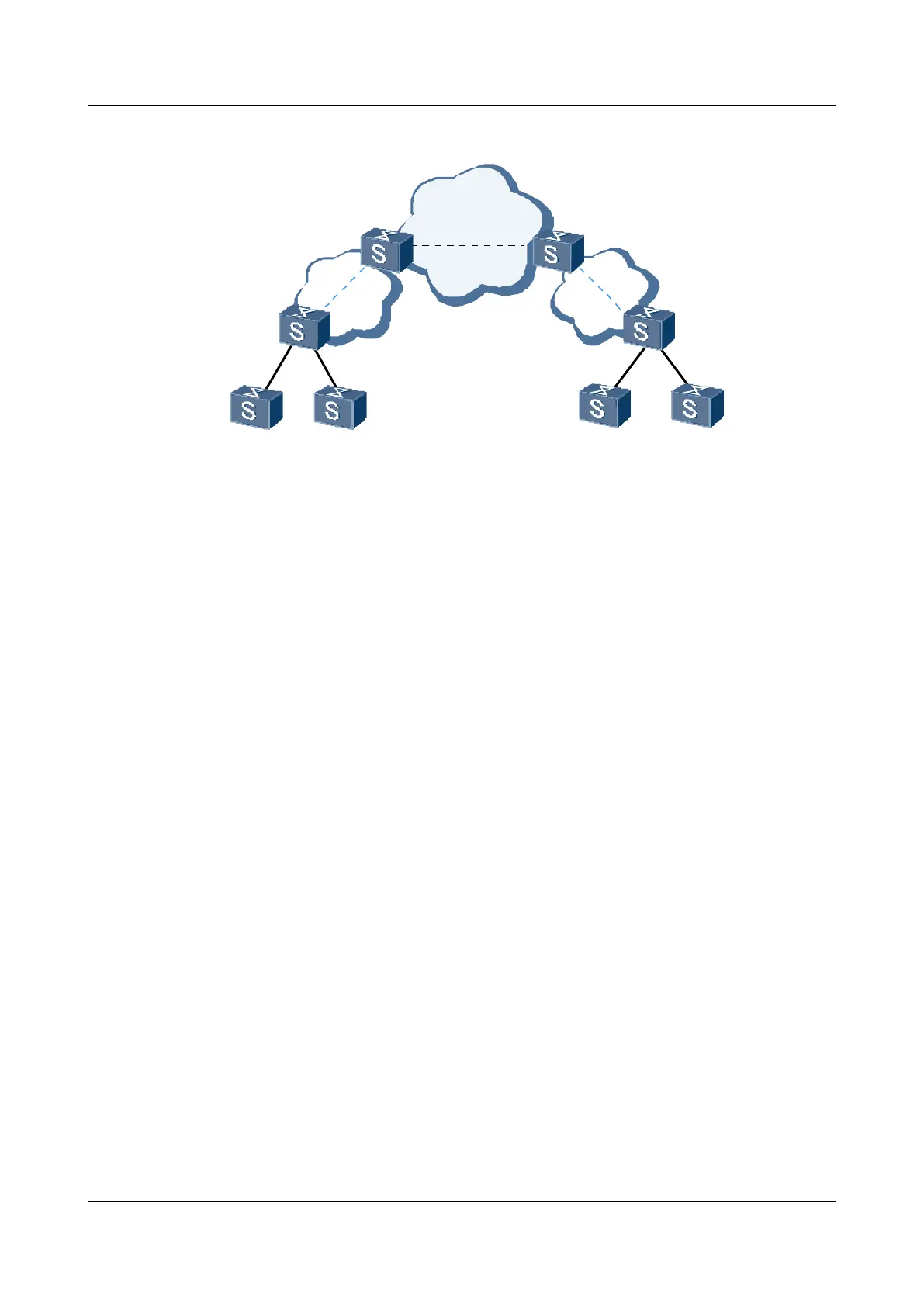
Figure 6-4 Networking diagram of static VLLs accessing the VPLS network
SPE1 SPE2
UPE1
UPE2
CE1
CE2
CE3
CE4
PW
VPLS
Network
VLL
VLL
As shown in Figure 6-4, the UPEs add double MPLS labels to packets sent by CEs. The outer
layer is a static LSP label and is switched when a packet passes through the devices on the access
network. The inner label is a VC label that identifies a VC. The inner label remains unchanged
when a packet is transmitted along the LSP. Packets received by an SPE contain double labels.
The outer label, which is a statically configured public network label, is popped up. The inner
label determines the VSI which the SVC accesses.
Inter-AS VPLS
Martini and Kompella VPLSs can implement inter-AS Option A. In the inter-AS VPLS
networking, the type of links between Autonomous System Boundary Routers (ASBRs) must
be the same as the type of VCs. If the number of inter-AS VCs is small, Option A can be used.
6.3 Configuring Kompella VPLS
This section describes how to use BGP as the VPLS signaling to configure Kompella VPLS and
how automatic discovery of VPLS PEs is implemented by configuring VPN targets..
6.3.1 Establishing the Configuration Task
6.3.2 Enabling BGP Peers to Exchange VPLS Information
6.3.3 Creating a VSI and Configuring the BGP Signaling
6.3.4 (Optional) Configuring Huawei Devices to Communicate with Non-Huawei Devices
6.3.5 Binding a VSI to an Interface of a CE
6.3.6 (Optional) Configuring the Features of Kompella VPLS
6.3.7 Checking the Configuration
Quidway S9300 Terabit Routing Switch
Configuration Guide - VPN 6 VPLS Configuration
Issue 03 (2009-08-20) Huawei Proprietary and Confidential
Copyright © Huawei Technologies Co., Ltd.
6-7

 Loading...


