4.11.3 Example for Configuring an SVC VLL
Networking Requirements
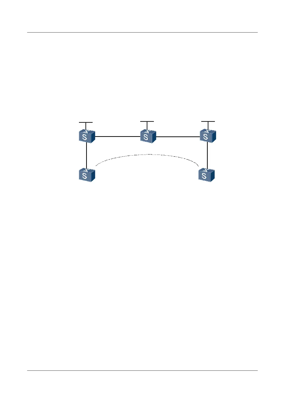
The CE is connected to the PE through a GE interface.
An SVC VLL is set up between CE1 and CE2. The SVC connection is created on PEs and the
VC label is specified.
Figure 4-6 Networking diagram for configuring SVC VLL
GE 2/0/0 GE 2/0/0 GE 1/0/0 GE 1/0/0
GE 1/0/0 GE 2/0/0
GE 1/0/0
GE 1/0/0
P
PE 2PE 1
CE 1 CE 2
Loopback 1
1.1.1.9/32
Loopback 1
3.3.3.9/32
Loopback 1
2.2.2.9/32
SVC
connection
S9300
Interface VLANIF interface IP address
PE1 GigabitEthernet1/0/0 VLANIF 10 -
GigabitEthernet2/0/0 VLANIF 20 10.1.1.1/24
Loopback1 - 1.1.1.9/32
PE2 GigabitEthernet1/0/0 VLANIF 30 10.2.2.1/24
GigabitEthernet2/0/0 VLANIF 40 -
Loopback1 - 3.3.3.9/32
P GigabitEthernet1/0/0 VLANIF 30 10.2.2.2/24
GigabitEthernet2/0/0 VLANIF 20 10.1.1.2/24
Loopback1 - 2.2.2.9/32
CE1 GigabitEthernet1/0/0 VLANIF 10 100.1.1.1/24
CE2 GigabitEthernet1/0/0 VLANIF 20 100.1.1.2/24
Configuration Roadmap
The configuration roadmap is as follows:
1. Enable MPLS and MPLS L2VPN.
2. Create a static L2VC connection between PEs and manually configure the VC label.
Quidway S9300 Terabit Routing Switch
Configuration Guide - VPN 4 VLL Configuration
Issue 03 (2009-08-20) Huawei Proprietary and Confidential
Copyright © Huawei Technologies Co., Ltd.
4-47

 Loading...


