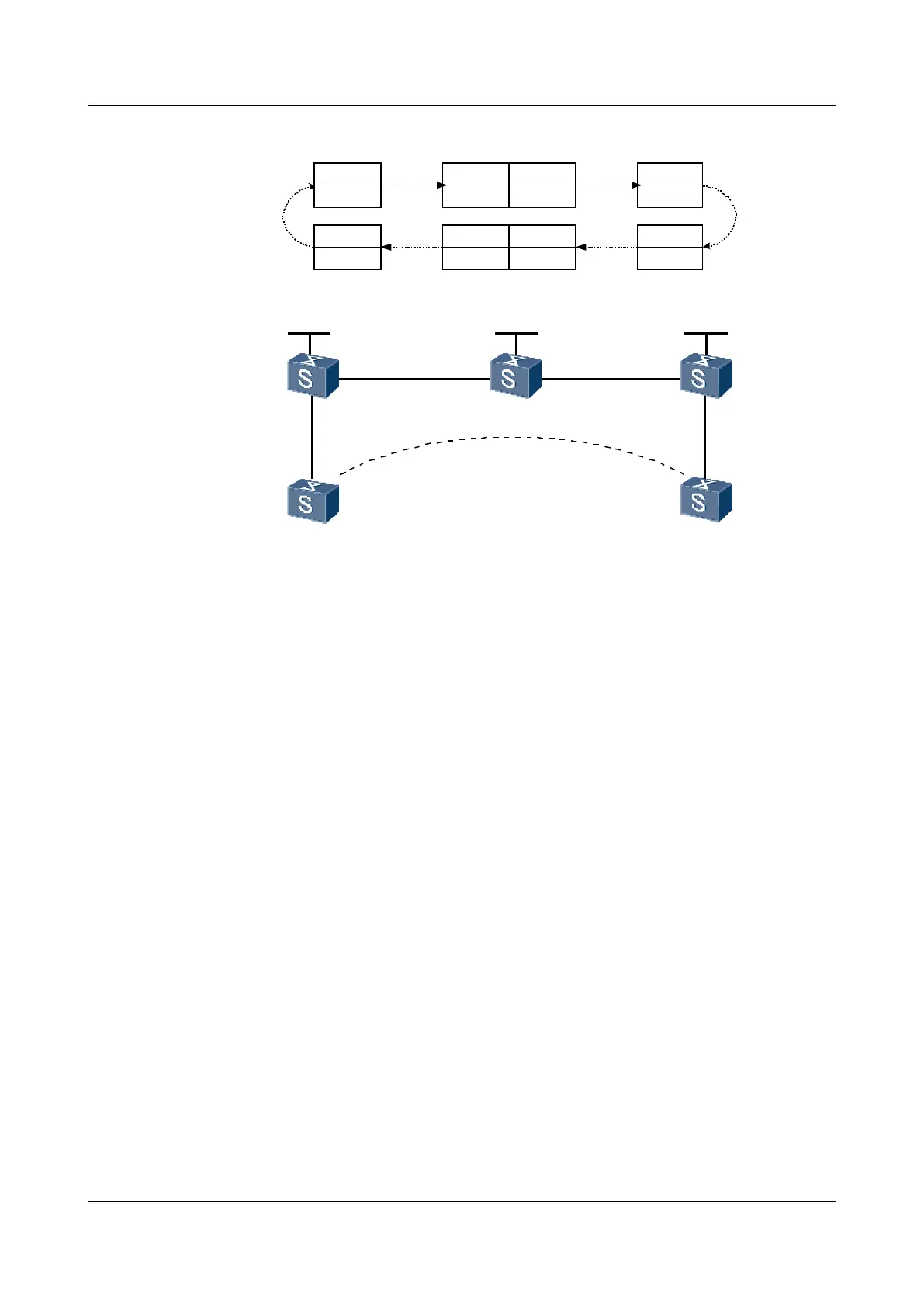
Figure 4-5 Networking diagram for configuring remote CCC connection
Loopback1
2.2.2.9/32
CCC remote
connection
GE 2/0/0
GE 2/0/0 GE1/0/0
GE 1/0/0
GE 1/0/0 GE 2/0/0
GE 1/0/0 GE 1/0/0
P
PE 2
PE 1
CE 1 CE 2
O-Label
200
I-Label
200
O-Label
201
I-Label
201
I-Label
100
O-Label
100
I-Label
101
O-Label
101
CE 1 to CE 2
CE 2 to CE 1
Loopback1
1.1.1.9/32
Loopback1
3.3.3.9/32
S9300 Interface VLANIF interface IP address
PE1 GigabitEthernet1/0/0 VLANIF 10 -
GigabitEthernet2/0/0 VLANIF 20 10.1.1.1/24
Loopback1 - 1.1.1.9/32
PE2 GigabitEthernet1/0/0 VLANIF 30 10.2.2.1/24
GigabitEthernet2/0/0 VLANIF 40 -
Loopback1 - 3.3.3.9/32
P GigabitEthernet1/0/0 VLANIF 30 10.2.2.2/24
GigabitEthernet2/0/0 VLANIF 20 10.1.1.2/24
Loopback1 - 2.2.2.9/32
CE1 GigabitEthernet1/0/0 VLANIF 10 100.1.1.1/24
CE2 GigabitEthernet1/0/0 VLANIF 40 100.1.1.2/24
Configuration Roadmap
The configuration roadmap is as follows:
1. Configure a bidirectional static LSP for the local CCC connection between PEs. The LSP
is exclusively used by the CCC connection.
2. Enable MPLS L2VPN on the PEs. MPLS L2VPN need not be enabled on P.
3. Set up two connections: one from CE1 to CE2 and the other from CE2 to CE1.
Quidway S9300 Terabit Routing Switch
Configuration Guide - VPN 4 VLL Configuration
Issue 03 (2009-08-20) Huawei Proprietary and Confidential
Copyright © Huawei Technologies Co., Ltd.
4-41

 Loading...


