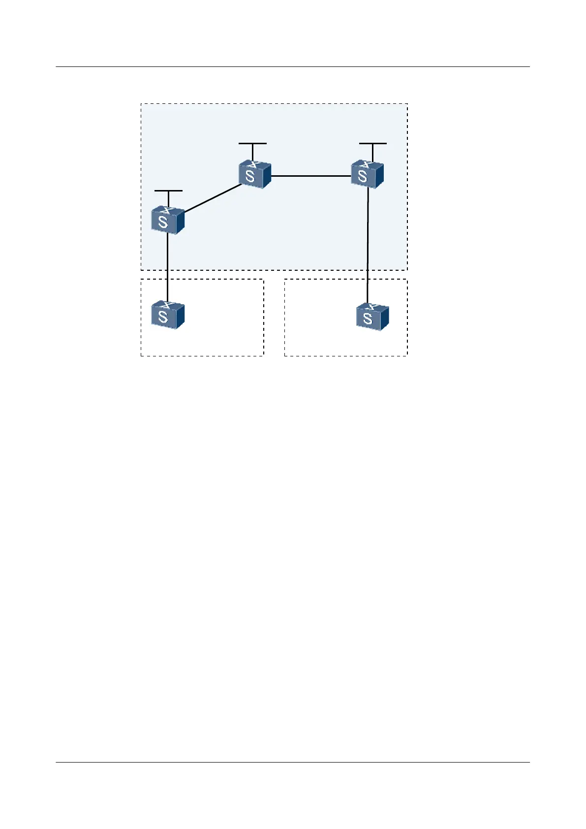
Figure 3-8 Networking diagram for configuring the HoVPN
AS: 65420
VPN-A
CE2
UPE
SPE
AS: 65410
VPN-A
CE1
GE2/0/0
GE2/0/0
AS: 100
Loopback1
1.1.1.9./32
Loopback1
3.3.3.9./32
GE1/0/0GE1/0/0
GE1/0/0
GE1/0/0
GE1/0/0
GE2/0/0
Loopback1
2.2.2.9./32
PE
S9300 Interface VLANIF interface IP address
UPE GigabitEthernet1/0/0 VLANIF 30 10.1.1.1/24
GigabitEthernet2/0/0 VLANIF 10 172.1.1.1/24
SPE GigabitEthernet1/0/0 VLANIF 10 172.1.1.2/24
GigabitEthernet2/0/0 VLANIF 20 172.2.1.1/24
PE GigabitEthernet1/0/0 VLANIF 40 10.2.1.2/24
GigabitEthernet2/0/0 VLANIF 20 172.2.1.2/24
CE1 GigabitEthernet1/0/0 VLANIF 30 10.1.1.1/24
CE2 GigabitEthernet1/0/0 VLANIF 40 10.2.1.1/24
Configuration Roadmap
The configuration roadmap is as follows:
1. Configure IGP on the backbone network so that PEs can learn the loopback address of each
other. Create MPLS LSPs between the PEs.
2. Create a VPN instance on UPE and set up an EBGP adjacency between UPE and CE1.
Create a VPN instance on PE and set up an EBGP adjacency between PE and CE2.
3. Set up an MP-IBGP adjacency between UPE and SPE, and between PE and SPE.
4. Create a VPN instance on the SPE and set the UPE as its under layer PE. Configure the
UPE to advertise the default route of the VPN instance.
Quidway S9300 Terabit Routing Switch
Configuration Guide - VPN 3 BGP/MPLS IP VPN Configuration
Issue 03 (2009-08-20) Huawei Proprietary and Confidential
Copyright © Huawei Technologies Co., Ltd.
3-107

 Loading...


