ospf 1
area 0.0.0.0
network 30.1.1.0 0.0.0.255
#
ospf 2
area 0.0.0.0
network 40.1.1.0 0.0.0.255
network 10.2.1.0 0.0.0.255
#
return
2.7.3 Example for Configuring the CE to Access a VPN Through a
GRE Tunnel of the Public Network
Networking Requirements
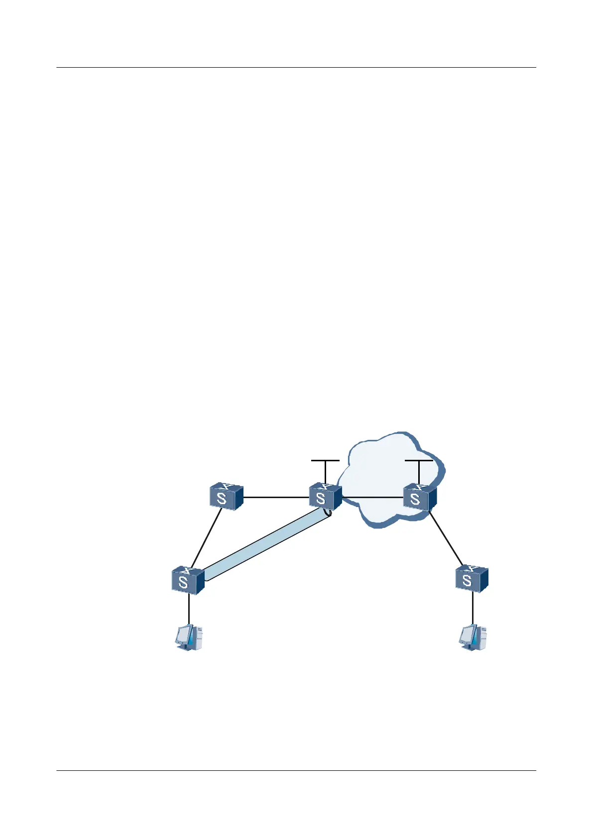
As shown in Figure 2-7,
l PE1 and PE2 are located in the MPLS backbone network.
l CE1 is connected to PE1 through S9300-A.
l CE2 is connected to PE2 directly.
l CE1 and CE2 belong to the same VPN.
CE1 and CE2 are required to interwork with each other.
Figure 2-7 Networking diagram in which CEs access a VPN through the GRE tunnel of the
public network
Tunnel
PC1 PC1
GE1/0/0
GE1/0/0
GE1/0/0
GE1/0/0
GE1/0/0
GE2/0/0
GE2/0/0
GE2/0/0
GE2/0/0
GE2/0/0
CE1 CE2
PE1
PE2
Tunnel1/0/0
Tunnel2/0/0
S9300-A
Loopback1
Loopback1
S9300
Interface VLANIF interface IP address
CE1 GigabitEthernet1/0/0 VLANIF 10 21.1.1.2/24
GigabitEthernet2/0/0 VLANIF 20 30.1.1.1/24
Tunnel2/0/0 - 2.2.2.1/24
2 GRE Configuration
Quidway S9300 Terabit Routing Switch
Configuration Guide - VPN
2-24 Huawei Proprietary and Confidential
Copyright © Huawei Technologies Co., Ltd.
Issue 03 (2009-08-20)

 Loading...


