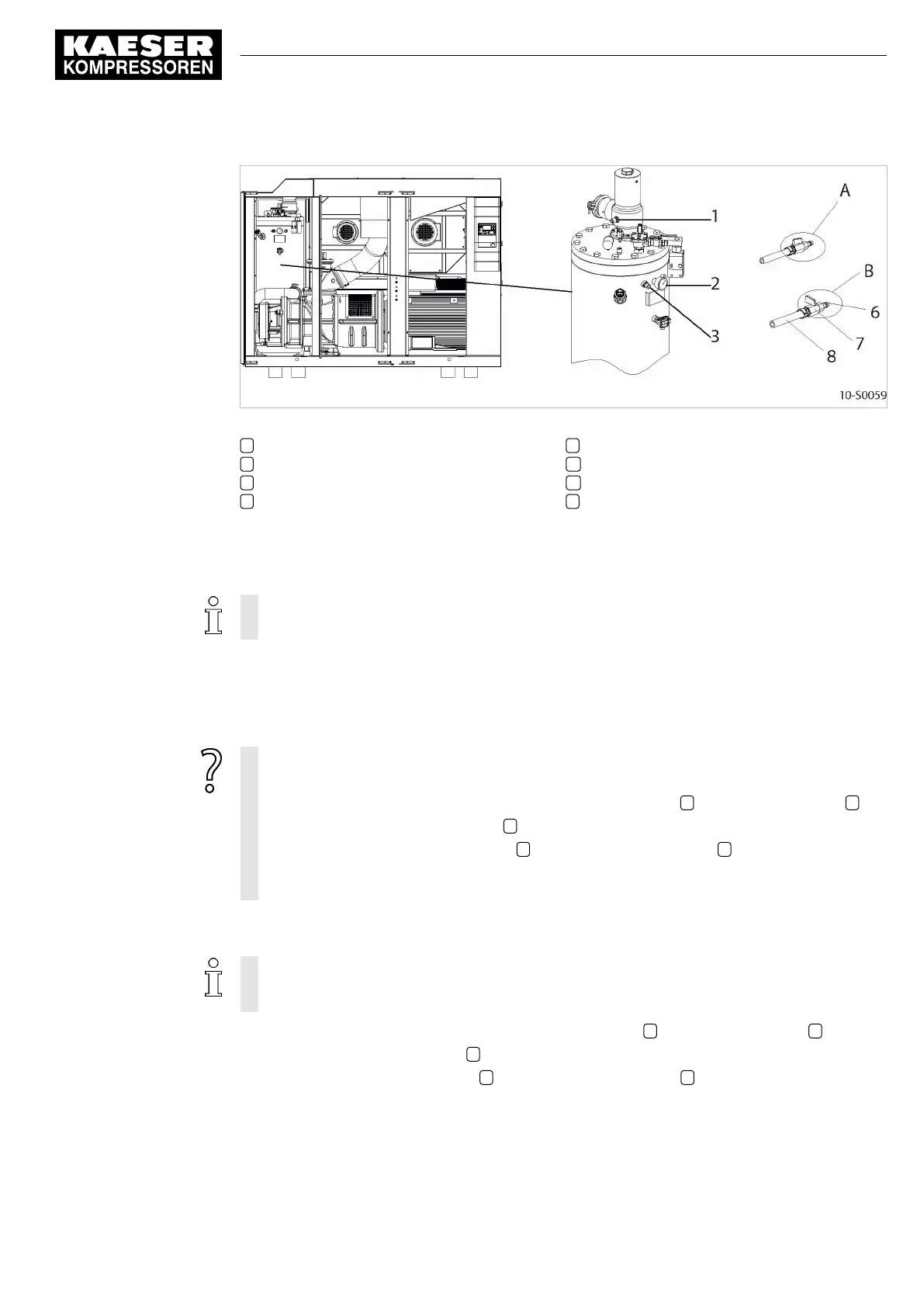
Fig. 28 Venting the machine
1 Hose coupling (gas cooler venting)
2 Pressure gauge
3 Hose coupling (oil separator tank venting)
6 Male hose fitting
7 Shut-off valve
A Shut-off valve open
B Shut-off valve closed
8 Maintenance hose
Isolate the compressor from the gas network
➤ Close the user's shut-off valve at the inlet and outlet ends.
If no shut-off valve is provided, the complete gas network must be vented.
Vent the oil separator tank
The oil circulation vents automatically as soon as the machine is stopped.
➤ Check that the oil separator tank pressure gauge reads 0 bar.
After automatic venting the pressure gauge does not read 0 bar?
➤ Make sure that the shut-off valve is closed or that the complete gas network is vented.
➤ With the shut-off valve closed, insert the male hose fitting 6 into the hose coupling 3 .
➤ Slowly open the shut-off valve 7 to release pressure.
➤ Disconnect the male hose fitting 6 and close the shut-off valve 7 .
➤ If manual venting does not bring the oil separator tank pressure gauge to zero: Contact
KAESER Service.
Vent gas manually from the gas cooler
After shutting down the compressor and venting the oil separator tank, the machine is still un‐
der pressure from the gas network or the section from the shut-off valve to the minimum pres‐
sure/check valve.
1. With the shut-off valve closed, insert the male hose fitting 6 into the hose coupling 1 .
2. Slowly open the shut-off valve 7 to release pressure.
3. Disconnect the male hose fitting 6 and close the shut-off valve 7 .
10 Maintenance
10.14 Venting the machine (de-pressurising)
ESD_2C_10357405_10–LIN_00 E
Service Manual Screw Compressor
ESD 442/14 bar (abs) SFC SIGMA CONTROL 2
67