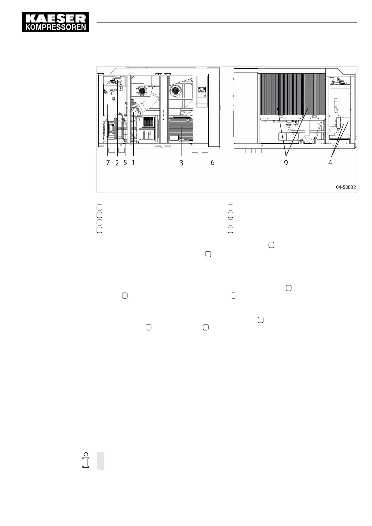
Fig. 5 Machine layout
1 Inlet valve
2 Minimum pressure/check valve
3 Compressor drive motor
4 Oil filter
5 Airend
6 Control cabinet
7 Oil separator tank
9 Oil/gas cooler
Gas delivered to the machine by pipeline is drawn into the airend 5 and compressed.
The airend is driven by an electric motor 3 .
Cooling oil is injected into the airend. It lubricates moving parts and forms a seal between the ro‐
tors themselves and between them and the airend casing. This direct cooling in the compression
chamber ensures a very low airend discharge temperature.
Cooling oil recovered from the compressed gas in the oil separator tank 7 gives up its heat in the
oil cooler 9 . The oil then flows through the oil filter 4 and back to the point of injection. Pressure
within the machine keeps the oil circulating. A separate pump is not necessary. A thermostatic
valve maintains optimum cooling oil temperature.
Compressed gas, freed of cooling oil in the oil separator tank 7 , flows through the minimum pres‐
sure / check valve 2 into the gas cooler 9 . The minimum pressure/check valve ensures that there
is always a minimum internal pressure sufficient to maintain cooling oil circulation in the machine.
The cooler brings down the compressed gas temperature to only 5 K to 10 K above ambient.
4.3 Frequency converter
The machine is equipped with a frequency converter that regulates motor speed in proportion to
the gas demand.
4.4 Floating relay contacts
Floating relay contacts are provided for the transfer of signals, messages.
Information on location, loading capacity and type of message or signal is found in the electrical
diagram.
If the floating relay contacts are connected to an external voltage source, voltage may be
present even when the machine is isolated from the power supply.
4 Design and Function
4.3 Frequency converter
ESD_2C_10357405_10–LIN_00 E
Service Manual Screw Compressor
ESD 442/14 bar (abs) SFC SIGMA CONTROL 2
27