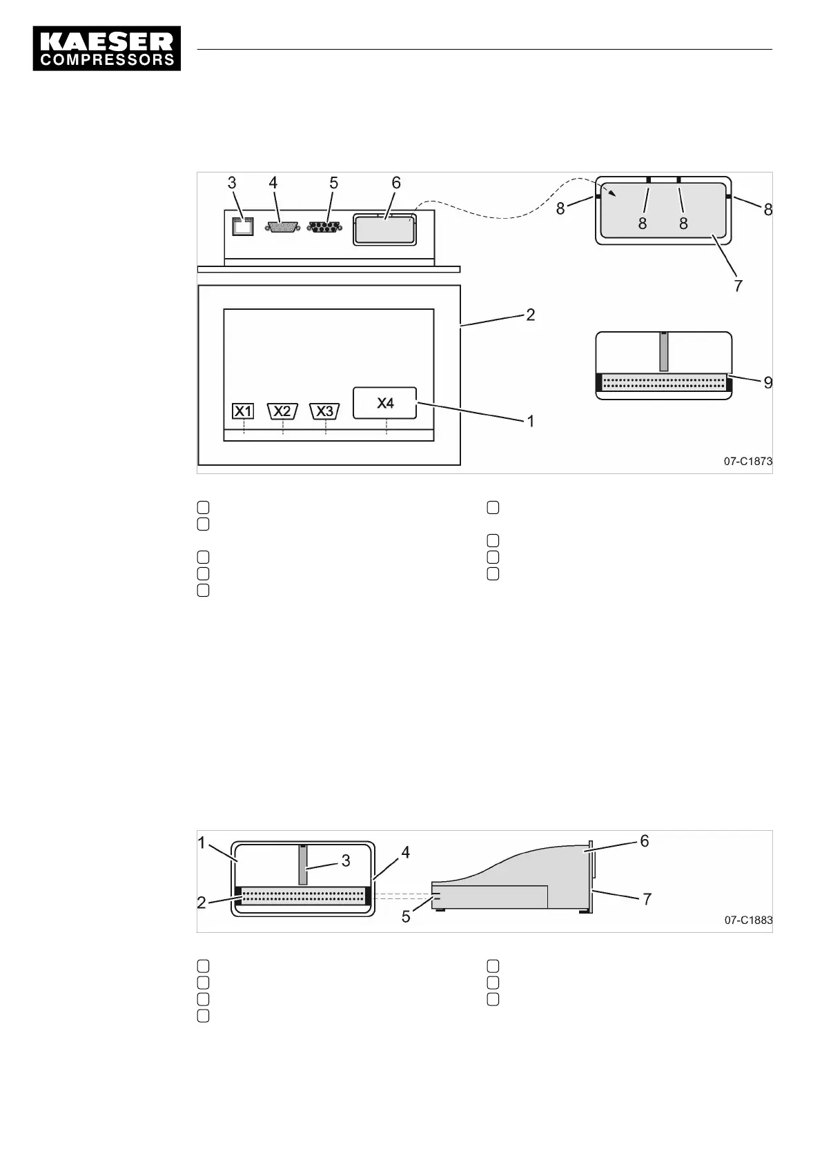
Proper removal of the plastic cover
Fig. 28 Communication interface
1 Designation of the interfaces
2 Rear side of the controller
SIGMA CONTROL 2
3 Ethernet interface X1
4 IO BUS X2
5 RS485–FC (USS interface) X3
6 Communication interface X4 (customer in‐
terface)
7 Plastic cover
8 Fin
9 Communication interface X4 without plastic
cover
1. Place the screwdriver next to the fin.
2. Insert the tip into the slot between the plastic cover and the enclosure of the
SIGMA CONTROL 2.
3. Press the screwdriver down until the fin breaks.
4. Break all other fins in the same manner.
5. Remove the plastic cover.
Inserting and fixing the communication module
Align the communication module until both cable connectors are at the same height.
Precondition The plastic cover is removed.
Fig. 29 Insert the communication module.
1 Bay, interface X4
2 Cable connector, interface X4
3 Guiding plate
4 Recess, module bay
5 Cable connector, communication module
6 Communication module
7 Front plate
7 Initial Start-up
7.9 Configuring the machine for master control
92
Service manual Controller
SIGMA CONTROL 2 SCREW FLUID 1.1.3 9_9450 03USE




 To Next Page