10.19 Assembling flexible pipe connections
With the machine depressurized, the clamping bolts must be freely movable by hand and par‐
allel with the pipe.
All clamping bolts must be equally loaded.
➤ Replace the self-locking nuts.
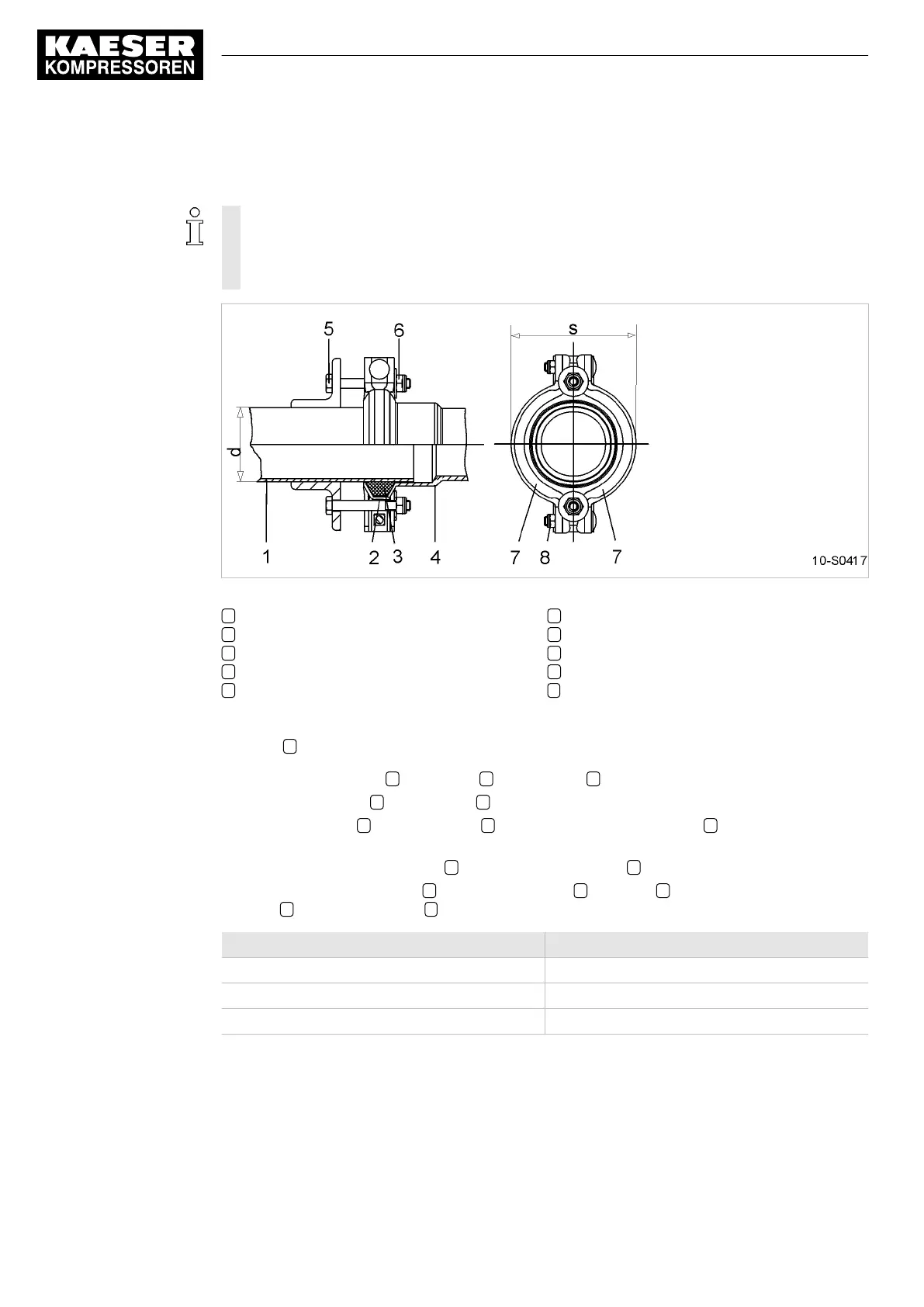
Fig. 37 Assembling flexible pipe connections
1 Pipe
2 Seal holder
3 Seal
4 Sleeve
5 Tensioning bolt
6 Self-locking nut
7 Pipe clamp halves
8 Self-locking nut
d Pipe diameter (outside)
s Dimension of the flexible pipe joint under
tension.
Precondition The pipe 1 must be deburred and the sealing face clean and undamaged.
1. Slide the seal holder 2 and gasket 3 over the pipe 1 .
2. Slide the pipe end 1 into the bush 4 without pretension.
3. Slide the gasket 3 with seal holder 2 up the sealing face of the bush 4 taking care of pipe
alignment.
4. Tighten up the clamping bolts 5 with the self-locking nuts 6 .
5. Lay the pipe clamp halves 7 over the seal holder 2 and bush 4 and tighten the self-locking
nuts 8 until the dimension s is reached.
Pipe diameter: d [mm] Clamp diameter: s [mm]
42.0 83.0 ± 2%
89.0 124.0 ± 2%
114.0 152.0 ± 2%
Tab. 40 Dimensions of the flexible pipe connection
10 Maintenance
10.19 Assembling flexible pipe connections
78
Service Manual Screw Compressor
ESD 442/14 bar (abs) SFC SIGMA CONTROL 2 ESD_2C_10357405_10–LIN_00 E