10.15 Replenishing the cooling oil
The machine must be isolated from the compressed gas network and completely vented be‐
fore undertaking any work on the pressure system.
Material The maintenance hose with hose coupling and shut-off valve needed for venting is stowed beneath
the oil separator tank.
Precondition The supply disconnecting device is switched off,
the device is locked off,
the absence of voltage has been verified.
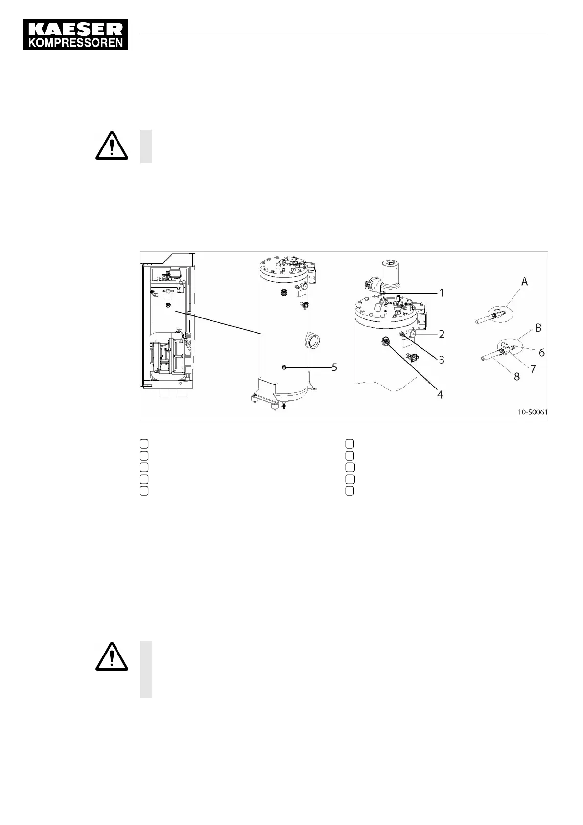
Fig. 29 Replenishing the cooling oil
1 Hose coupling (gas cooler venting)
2 Pressure gauge
3 Hose coupling (oil separator tank venting)
4 Oil filler port with plug
5 Cooling oil level indicator
6 Male hose fitting
7 Shut-off valve
A Shut-off valve open
B Shut-off valve closed
8 Maintenance hose
1. Vent the machine as described in section 10.15.1.
2. Fill with cooling oil and test run as described in section 10.15.2.
10.15.1 Venting the machine (de-pressurising)
Venting takes place in three stages:
■ Isolate the compressor from the gas system.
■ Vent the oil separator tank.
■ Gas is vented manually from the gas cooler.
CAUTION
Escaping oil mist is damaging to health.
➤ Do not direct the maintenance hose at persons while venting.
➤ Do not inhale the oil mist.
10 Maintenance
10.15 Replenishing the cooling oil
68
Service Manual Screw Compressor
ESD 442/14 bar (abs) SFC SIGMA CONTROL 2 ESD_2C_10357405_10–LIN_00 E
 Loading...
