Indicators
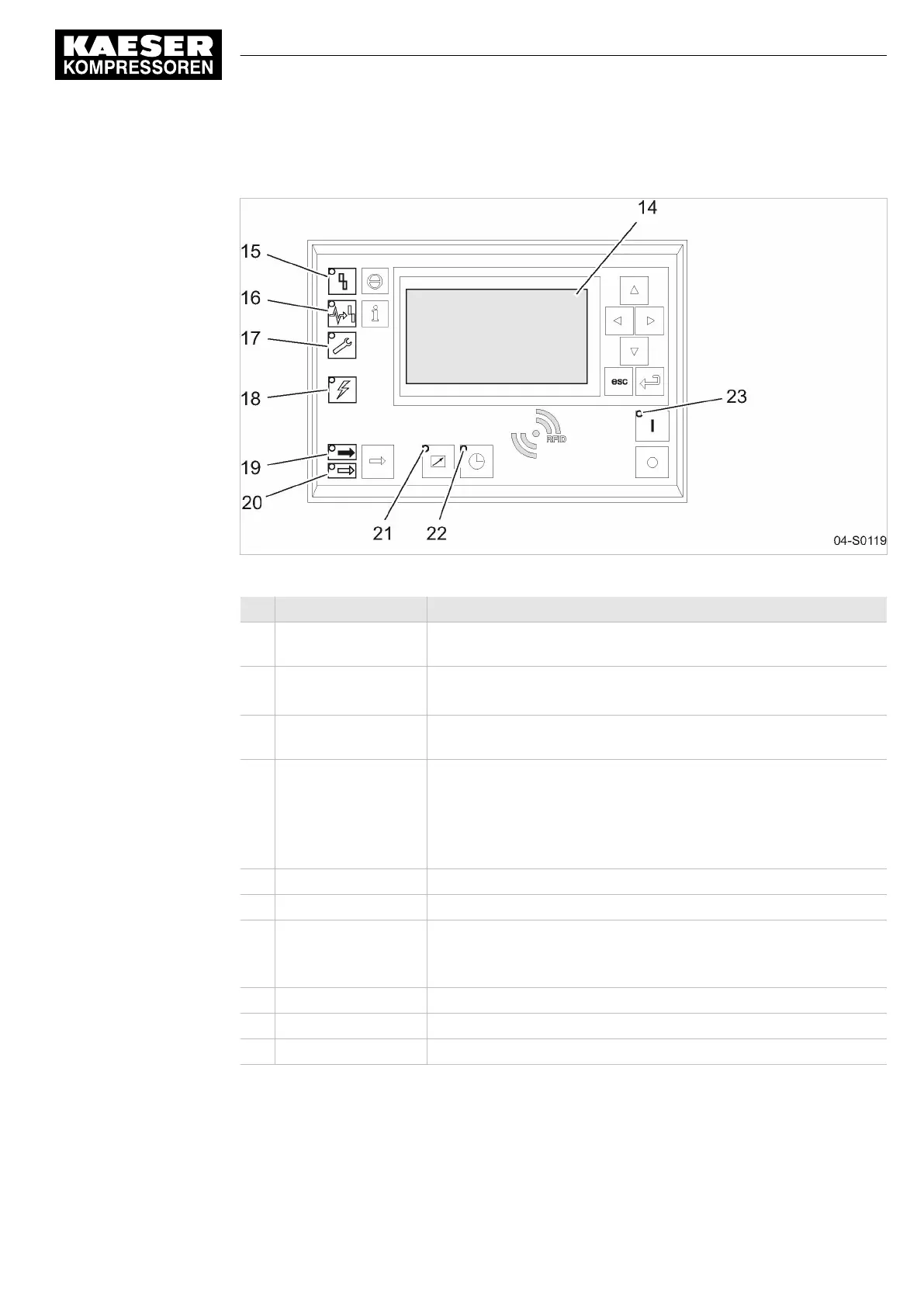
Fig. 9 Indicators - overview
Item Description Function
14 Indicator field or dis‐
play
Graphic display with 8 lines and 30 characters.
15
Alarm
Flashes red when an alarm occurs.
Lights continuously when acknowledged.
16
Communication
Continuous red illumination if a communication connection (Ethernet,
USS, COM modules) has a fault.
17
Warning
Flashes in yellow in the following events:
■ maintenance work due,
■ Warning message
Lights continuously when acknowledged.
18
Controller voltage
Lights green when the power supply is switched on.
19
LOAD
Lights green when the compressor is running under LOAD.
20
IDLE
Lights green when the compressor is running in IDLE.
Flashes when the «LOAD/IDLE» toggle key is pressed (key inactive
for gas compressors).
21
Remote control
The LED lights when the machine is in remote control.
22
Shift clock
The LED lights when the machine is in clock control.
23
Machine ON
Lights green when the machine switched on.
Tab. 29 Indicators
4 Design and Function
4.9 Operating panel SIGMA CONTROL 2
ESD_2C_10357405_10–LIN_00 E
Service Manual Screw Compressor
ESD 442/14 bar (abs) SFC SIGMA CONTROL 2
31