2. Press «Enter» to switch into setting mode.
Quality range
flashes.
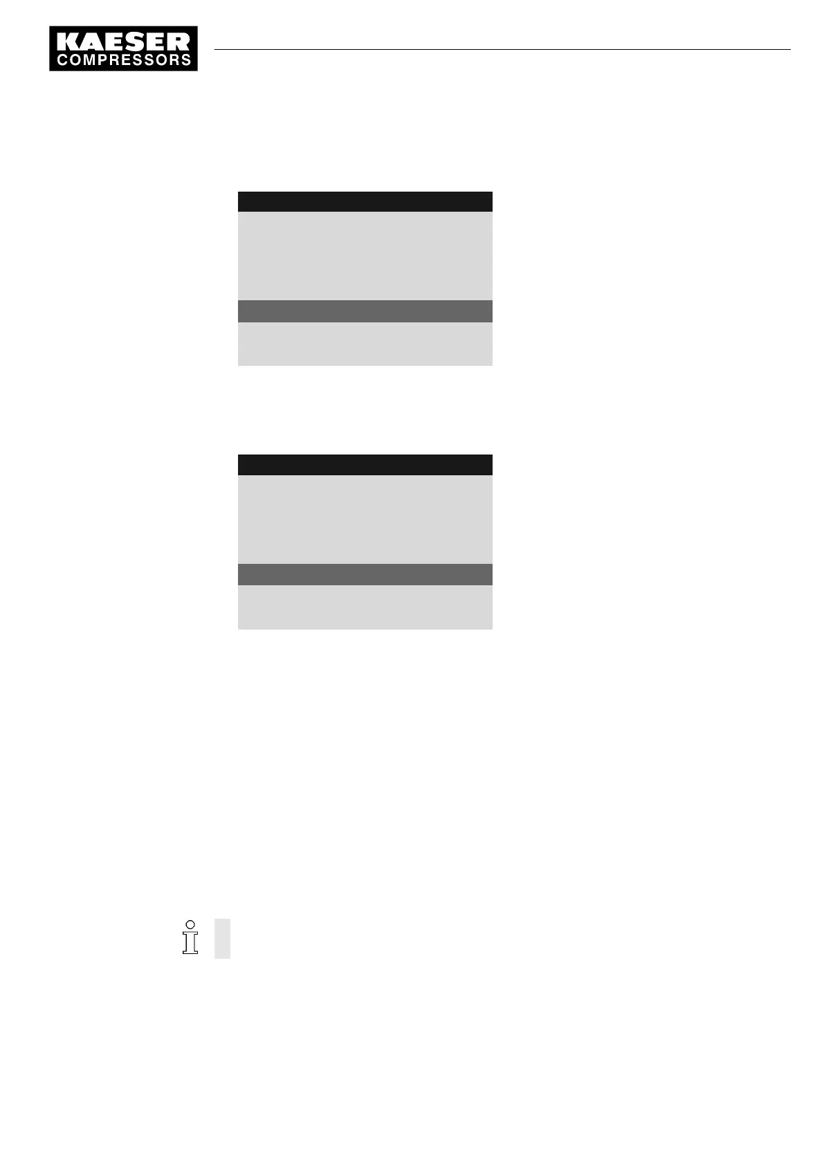
8 9 p s i 0 8 : 1 5 1 7 6 ° F
5.7.2.2.5 AI_I_1
Menu
Volume flow 01.
The line for sensor designation
AII 1.03 ok ☑ 123 m
3
/h
Measured value prior to calibration
·········
20mA : 16000¦ 4mA: 0
Signal top range/signal bottom range
3. Press and hold the «DOWN» key and to set the top of the range to 50.
The quantity reduces initially in steps of units, then tens, hundreds and finally in thousands.
4. Using this method, reduce the value to 100 and then set to 50 with the «DOWN» key.
5. Press the «Enter» key to accept the value.
8 9 p s i 0 8 : 1 5 1 7 6 ° F
5.7.2.2.5 AI_I_1
Menu
Volume flow 01.
The line for sensor designation
AII 1.03 ok ☑ -12 m
3
/h
Measured value after calibration
·········
20mA : 50¦ 4mA: 0
Signal top range/signal bottom range
6. Set the value for the bottom range (4 mA) to zero accordingly.
The measured value adjusts to the calibration.
Result The signal value from the sensor can now be displayed in the
< Performance data >
menu (see
chapter 8.7).
7.11.3 Displaying additional binary input signals
As well as the defined fault and warning messages there are six additional, freely selectable input
signals that can be used to display messages. A list of the defined fault and warning messages is
provided in chapters 9.2 and 9.5. Information on spare inputs is given in the machine circuit dia‐
gram.
An input signal can be classified as either a fault, a service or an operational message. To sup‐
press any possible contact bounce or similar problems, the input signal can be delayed by an ad‐
justable period. This ensures that the signal must be apparent for a minimum period before it can
be processed as a message.
If an input signal is classified as fault, the controller goes into the alarm state and shuts down
the machine.
Overview
Navigate to the
< Configuration ➙ I/O periphery ➙ External messages >
menu for the configura‐
tion.
■ Enter the message text
7 Initial Start-up
7.11 Configuring input and output signals
9_9450 03USE
Service manual Controller
SIGMA CONTROL 2 SCREW FLUID 1.1.3
129